Physical Description
Table 2–6 (Cont.)
IDE Disk Connector Pin-Out (J18)
Pin
Number
Function
Pin
Number
Function
7
Data 5
8
Data 10
9
Data 4
10
Data 11
11
Data 3
12
Data 12
13
Data 2
14
Data 13
15
Data 1
16
Data 14
17
Data 0
18
Data 15
19
Ground
20
No connection
21
DMA REQ
22
Ground
23
IOWC
24
Ground
25
IORC
26
Ground
27
IO CH RDY
28
Idebale
29
DMA Grant
30
Ground
31
Interrupt
32
IOCS16
33
A1
34
No connection
35
A0
36
A2
37
SEL 0
38
SEL 1
39
Busy
40
Ground
2.2.2.7
ISA Slot Connectors (J20–J24)
The AXPpci 33 supports five ISA option slots (J20–J24). Three slots
support short ISA modules; two support long ISA modules. See Section 2.4
for further details about ISA option modules.
The ISA option in slot 1 (J24) occupies the same bulkhead that the PCI
option in slot 3 (J25) occupies, making the slots mutually exclusive.
For definition of signal and power pin assignments, refer to the ISA
specification referenced in the Preface.
2.2.2.8
Keyboard Connectors (J39 and J38)
The AXPpci 33 is orderable with either the AT style (J39) 5-position
DIN keyboard connector or with a 6-position mini-DIN PS/2 style (J38)
keyboard connector. These connectors are mutually exclusive. The PS/2
style MLB also includes a PS/2 style mouse connector (see J40). Digital
UNIX does not support the serial mouse or AT style keyboard.
CAUTION: Use +5 V for the keyboard or pointing device only. Do not exceed
250 mA.
Table 2–7 lists the pin numbers and functions of the AT style keyboard
connector.
2–9
Содержание AXPpci 33
Страница 10: ......
Страница 14: ......
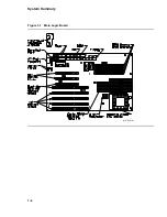
Страница 18: ...System Summary Figure 1 1 Main Logic Board MR 6391 AI 1 4...
Страница 22: ...Physical Description Figure 2 2 MLB Mechanical Drawing MR 6414 AI 2 4...
Страница 23: ...Physical Description Figure 2 3 MLB Component Outline Drawing MR 6401 AI 2 5...
Страница 46: ......
Страница 64: ......
Страница 70: ......
Страница 98: ......


