digico D5T Скачать руководство пользователя страница 133

7-7

Chapter 7

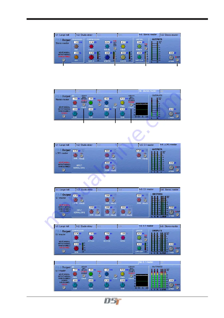
Main Channels Dynamics

Provides 

Crossover

 adjustment, 

3 band compression

 and 

Limiting.

Click here to change

parameter view

Click here to view

Threshold

Attack

Release

Ratio

Click here to view

Limiter

Threshold or Release

Processing In/Out

Main EQ

Provides 

4 Band EQ 

with adjustable Filter Types on Bands 1 and 4.

Click here to change

Band 1 Filter Type

Click here to change

Band 4 Filter Type

Set EQ Flat

LCRS Master

The controls for an LCRS Master are the same as stereo (See previous section) but the Input and Output Normalising panels allow
separate Gain and Phase control for each of the four signals.

5.1 Master

A 5.1 Master provides separate Input and Output Normalising for each of the six signals and in addition the 

Sub Channel

 has its own

Compressor, Limiter and 4 Band EQ.

Sub Channel Dynamics

Sub Channel EQ

Содержание D5T

Страница 1: ...Operation Manual Issue A September 2004 Software Versions 2 4...

Страница 2: ......

Страница 3: ...gistering the Product is deemed an acceptance of the terms and conditions in this agreement 3 The Product and its licence are not transferable and the Customer is not permitted to onward license to an...

Страница 4: ...ould you have any questions concerning this Agreement or if you desire to contact Embedded System Manufacturer for any other reason please refer to the address provided in the documentation for your e...

Страница 5: ...7 1 3 12 Dynamics 1 17 1 3 13 Auxiliaries 1 18 1 3 14 Control Groups 1 19 1 3 15 Master Fader Banks 1 20 1 3 16 Monitoring 1 21 2 1 The Input Channels 2 3 2 1 1 Channel Assignment 2 3 2 1 2 Worksurfac...

Страница 6: ...2 6 Meters 3 6 3 2 7 Output Channel Routing 3 6 3 2 8 Buss Signals as Input Sources 3 7 3 2 9 Headphones 3 7 3 2 10 Output Insert 3 7 3 3 The Matrix 3 8 3 3 1 Matrix Inputs 3 8 3 3 2 Matrix Processing...

Страница 7: ...7 Transport Timecode Configuration 4 21 4 8 Audio Synchronisation 4 22 4 8 1 Internal Sync Console As Master 4 22 4 8 2 External Sync 4 22 4 8 3 External Sync Sources 4 23 4 8 4 Sample Rate and Conve...

Страница 8: ...s 5 19 5 3 11 Machine Control 5 20 6 1 Real Time Automation 6 2 6 1 2 Isolate Mode 6 2 6 1 3 Record Mode 6 2 6 1 4 Play Update Mode 6 3 6 1 5 Automation Options 6 3 6 1 6 Safe Mode Dynamic Automation...

Страница 9: ...A 6 Masters A 6 A 7 Cue Control A 6 A 8 Global Safe and Mute Buttons A 7 A 9 Macros A 7 Appendix B Multiple Console Setups B 3 B 1 1 Front Of House and Monitors Setup B 3 B 1 2 Gain Tracking Settings...

Страница 10: ......

Страница 11: ...Chapter 1 1 1 Chapter 1 Getting Started...

Страница 12: ...Chapter 1 1 2...

Страница 13: ...ront of House and or Monitoring consoles Remote control of console via an ethernet link with a laptop computer The D5 TC Theatre Masters Controller provides extended master fader controls eight progra...

Страница 14: ...B STAGE RACKS CONNECTION WITH OPTICAL FIBRE OPTO A OPTO ID 30 OPTO ID 20 FOH AUDIO SYNC OPTO OPTO ID 32 OPTO A OPTIONAL REDUNDANT LOOP OPTO A OPTO B OPTO B OPTO B MAIN MADI IN LOCAL RACK MAIN MADI OU...

Страница 15: ...he example below shows the settings for a system with a Main Front of House console and its Redundant Engine a Monitor console and its Redundant Engine and a Remote Controlller or Theatre Controller f...

Страница 16: ...Low Pass Filters Dynamics Thresholds and On Off Joystick Undo Redo Button Channel Fader Banks Master Section Meter Status Master Fader Banks Master Screen Screen Scroll Mute and Interactive LCD Funct...

Страница 17: ...gue Gain Digital Trim Input Gain Phase Aux Send Compressor Controls Screen Scroll Assign Rotary Assign Button Channel Fader LCD Function Aux Send Gate Controls Mute Interactive LCD Button Aux On Off C...

Страница 18: ...t Fader for the new session Remember that when all settings are cleared any labelling or routing which you have done will be lost 1 3 2 Consoles and Racks If the console is the only one in the system...

Страница 19: ...le will send its settings to the racks and change them accordingly For more information on the use of this panel please see the chapter on Multiple Console Setups 1 3 3 Selecting an Input Source First...

Страница 20: ...2 3 4 5 If the Stereo is pressed the input channel functions will control two input signals the one which has been selected and the next one in the rack eg If Stage 1 is selected and the stereo button...

Страница 21: ...nput screen again to return to the standard view 2 3 4 1 To Route to a Direct Output 1 Touch the bottom of the input screen to open the routing panel 2 Touch the Directs button if it is not already hi...

Страница 22: ...e panel 4 Touch the name of the Socket Group that contains the output you require eg Loc op 1 8 5 Touch the Output Socket button s that you require eg Loc op 1 Loc op 2 etc 6 Touch the Route button at...

Страница 23: ...ones you wish to adjust and they will become highlighted Use the worksurface Matrix Send control and On Off switch to adjust the settings for all highlighted sends At the bottom of the panel there ar...

Страница 24: ...ls may be routed to a pre EQ pre fader direct output and or a post fader output To Route a Matrix Group to a post fader Output 1 Touch the bottom of the matrix group screen to open the routing panel 2...

Страница 25: ...l 2 Touch the Direct button if it is not already highlighted 3 Touch the name of the Socket Group to view the output socket names 4 Touch the Output Socket button s that you require eg Loc op 1 Loc op...

Страница 26: ...he Session Title box and type a description of the session if required 6 Touch the Save button in the bottom right of the panel to save the session file Note If you touch a session name on the existin...

Страница 27: ...s In Out Note The four band EQ and each of the filters have their own in out switches The type of filter used by bands one and four can be changed by successive presses of the Curve Select button for...

Страница 28: ...used as auxiliary sends pans on off and pre post switches in the following way FIRST MONO AUX SEND SECOND MONO AUX SEND FIRST MONO AUX ON OFF PRE POST WHEN SEND IS DOWN SECOND MONO AUX ON OFF PRE POS...

Страница 29: ...o Mute button if required to select this mode for the Control Group With Auto Mute on any Control Group member which is removed from the group will be automatically muted and any member that joins a g...

Страница 30: ...1 3 15 Master Fader Banks The faders in the console Master section control the output levels for busses auxiliaries and the matrix To select a bank press the relevant Master Fader Bank button for the...

Страница 31: ...ton can be independently assigned to use Solo 1 or Solo 2 Output solos may use a total of 16 inputs to each solo buss Therefore if the console was being used for stage monitors the first solo buss cou...

Страница 32: ...Chapter 2 2 1 Chapter 2 Inputs and Console Channels...

Страница 33: ...Chapter 2 2 2...

Страница 34: ...ics Thresholds and On Off Joystick Undo Redo Button Channel Fader Banks When you want to access an input channel which is not currently visible on a worksurface channel press the relevant Fader Bank b...

Страница 35: ...utput Gain Set Pan position Insert Send Gain Insert In Out Direct Output PreM Pre Post Assign Rotary Assign Switch Status Display HOLD The on screen channel strip is normally coloured grey but one or...

Страница 36: ...switch the relevant processing module ON or OFF There is also an option to assign a channel by either touching its fader or pressing its solo button See Section 2 2 8 Channel LCD Function Buttons 2 2...

Страница 37: ...The Misc group contains the console s internal signal sources and sockets including signals from the worksurface and rear Talkback microphones and the internal Noise and Tone generators The original...

Страница 38: ...controlled in the Sockets File Channel Aliases and Presets The Aliases button allows you to store or recall a complete channel setup An Alias is the name of a channel and a Preset can be associated w...

Страница 39: ...at zero and fader at 0dB The Close button removes the Preset Selector from the screen but has no direct effect on the channel settings Gain Phase and Delay When the Input module is expanded the rotar...

Страница 40: ...rols not for the whole channel Flat Button The Flat button forces all controls on the channel s EQ section to their default settings Equalisers Filters two and three blue and green are swept parametri...

Страница 41: ...es to open once the signal level has risen above threshold The Decay time sets the time the Gate takes to close once the signal level has dropped below the threshold and the Hold time has passed see n...

Страница 42: ...lters are used in the side chain of the gate to provide frequency conscious gating In this configuration the filtered signal feeds the input of the gate while other frequencies bypass the gate This al...

Страница 43: ...es depending on the availability of bussing resources Auxiliaries can be mono or stereo and stereo Auxiliaries have a Pan control as well as the normal Send Level control The Aux send rotaries below t...

Страница 44: ...inputs simultaneously controls the position of both left and right signals The joystick and wheel directly control the position of the left signal and the right signal is automatically mirrored on the...

Страница 45: ...g of the channel to additional Groups is indicated by dots If the channel is a member of a Control Group the name of that group also appears here Routed to Master and other group s no direct routing R...

Страница 46: ...er and type of SubGroups depends on the console configuration Direct Outputs You can also choose to route the channel signal directly to any of the console s output sockets by touching the Directs but...

Страница 47: ...Trim Meter Touch to Select Send Socket Socket Selector Insert On Off Insert On Off Touch to Select Return Socket Touch Here to Open Close Panel Worksurface Control The Insert can be PRE or POST EQ and...

Страница 48: ...and routing the first one NOTE In examples 3 4 5 and 6 the functions are limited to consecutive channels in the same view mode 2 2 7 Undo Redo Button While a channel is assigned to the EQ Dynamics Jo...

Страница 49: ...olo button again to return to the standard view MIC 1 01 Mo LCD FUNCTION SOLO SAFE AUX SEND FADERS BUILD GANGS FADER ASSIGNS CHANNEL SOLO ASSIGNS CHANNEL MIC 2 02 Mo MIC 3 03 Mo MIC 4 04 Mo MIC 5 05 M...

Страница 50: ...NCTION MIC 1 01 Mo LCD FUNCTION MIC 2 02 Mo MIC 3 03 Mo MIC 4 04 Mo MIC 5 05 Mo MIC 6 06 Mo MIC 7 07 Mo MIC 8 08 Mo PFL PFL PFL PFL PFL PFL PFL PFL AUX1 AUX2 AUX3 AUX4 AUX5 AUX6 AUX7 AUX8 MASTER SECTI...

Страница 51: ...any time by entering the Build Gangs mode as described in section 2 3 1 To remove a member of the gang press the relevant highlighted LCD Buttons and they will return to their original colour and no...

Страница 52: ...the console s worksurface screens have an equivalent SVGA video output on the back of the console and therefore any of the input screens can be duplicated to an external colour monitor Input screens...

Страница 53: ...ll or Large buttons on the right 2 4 3 Channel Banks The naming and assignment of the worksurface Fader Banks is controlled from the Channel Banks panel in the Layout menu on the MasterScreen To Name...

Страница 54: ...rface Master Fader Banks is controlled from the Master Fader Banks panel in the Layout menu on the Master Screen To Name a Master Fader Bank touch the existing name eg CG 1 8 and type a new one To inc...

Страница 55: ...stination ranges leaving intervening channels alone Move and Swap have the same effect if the source and destination ranges overlap After a Move or a Swap the selections are cleared but the panel rema...

Страница 56: ...ssing unrouted channels is available otherwise they will appear as mono 2 4 7 Duplicate Channel Where Copy Channels only duplicates each of a block of channels once the Duplicate Channel panel allows...

Страница 57: ...e worksurface hold down the relevant bank button on the worksurface and touch the on screen bank that you wish to assign The Set 0dB and Set oo buttons may be used to reset all or selected fader level...

Страница 58: ...Chapter 3 3 1 Chapter 3 Busses and Outputs...

Страница 59: ...3 2 Chapter 3...

Страница 60: ...guration but the layout will look something like this Scrolling the Master Screen If the console configuration is using more than the 24 outputs which the screen can display you can scroll the screen...

Страница 61: ...he expanded view of the buss meter will restore the display back to the single fader mode 3 2 Output and Buss Controls Once an output channel is expanded you can access its controls Buss Control butto...

Страница 62: ...from the highest numbered available input channels If insufficient channels are available a message is displayed quoting the number required If any of the input channels routed to thesub group are als...

Страница 63: ...ouching the Mute button on the screen or the worksurface cuts the output signal from the relevant buss 3 2 6 Meters The Meters display the signal level and indicate a peak level 3 2 7 Output Channel R...

Страница 64: ...by the monitor solo1 signals and there is a dedicated level control in the worksurface Monitor section on the right hand side of the worksurface 3 2 10 Output Insert In the buss master routing panel t...

Страница 65: ...t which ones you wish to adjust and they will become highlighted Use the worksurface Matrix Send control and On Off switch to adjust the settings for all highlighted sends At the bottom of the panel t...

Страница 66: ...s may be routed to a pre EQ pre fader direct output and or a post fader output To Route a Matrix Group to a post fader Output 1 Touch the bottom of the matrix group screen to open the routing panel 2...

Страница 67: ...l 2 Touch the Direct button if it is not already highlighted 3 Touch the name of the Socket Group to view the output socket names 4 Touch the Output Socket button s that you require eg Loc op 1 Loc op...

Страница 68: ...4 1 Chapter 4 Chapter 4 Master Section...

Страница 69: ...Chapter 4 4 2...

Страница 70: ...lkback Cues Monitoring Matrix Controls Master Mute Flip Master Fader Banks Master Fader Mute and Interactive LCD Function Button Master Fader Banks Output Control Group Faders Next Cue Button Previous...

Страница 71: ...l Display Brightness Use On Screen Touch Keyboard activates a touch sensitive keyboard which will automatically appear on screen when any label button Channel name control group etc is pressed While e...

Страница 72: ...er consoles in the system should not be highlighted at all The MADI Rack s connect states Receive Only and Full Connect are enabled disabled and set according to the Audio Master active state an inact...

Страница 73: ...ctions are handled in the Session Files Menu which is accessed by touching the button on the Master Screen 4 2 2 The New Session Panel To create a new session touch the Session Files button on the mas...

Страница 74: ...ight hand side of the screen These include the removable drive that can be plugged into the USB Data Port on the meter bridge Simply select the drive you require in the bottom left corner and then ope...

Страница 75: ...igned for use with a key ring style data card To use this facility insert the card into the USB Data Port and it will be recognised as an external drive It will then appear in the Load and Save panels...

Страница 76: ...ring The Monitoring panel can be found under the Setup Menu in the Master Screen and some of the controls can be accessed on the right hand side of the Master worksurface It may be accessed at any tim...

Страница 77: ...N FADERS SOLO 1 OR 2 ASSIGN FADERS UNASSIGN FADERS SOLO 1 OR 2 AFL2 AFL AFL AFL AFL AFL AFL AFL Aux 01 Aux 02 Aux 03 Aux 04 Aux 05 Aux 06 Aux 07 Aux 08 A01 0 LCD FUNCTION A02 0 A03 0 A04 0 A05 0 A06 0...

Страница 78: ...lt Meter Monitors The meters will show the selected type of monitor signal Master buss or PFL AFL Destructive SIP Meter Selected Busses The meters in the console s Master section can be assigned to an...

Страница 79: ...will open the following panel IMPORTANT NOTE The easiest method of doing this is to Quit To Windows and then reload D5T software from there If you are holding the SHIFT Key when Windows is reloading...

Страница 80: ...from any input signal the Local Top mic the Rear Mic Tone or Noise using the buttons at the top of the Channel Both channels could be sourced from the same mic but each one could route to different ou...

Страница 81: ...board Changing Talkback Presets Any changes you make to the talkback mic routing while a preset is selected is automatically stored as part of that preset 4 4 Control Groups 4 4 1 Creating Control Gro...

Страница 82: ...ual channel faders 4 4 2 Naming Control Groups Like inputs or busses Control Groups can be named by touching the name display on the screen default CG1 CG2 etc and typing a new name on the console key...

Страница 83: ...ess the Safe button 3 Press the Master LCD buttons for the Masters that should be Safe they will turn red and a tick will appear 4 Press the Master LCD Function button to exit Safe mode 5 Press the So...

Страница 84: ...SOLO ASSIGNS AUX ROT SOLO ASSIGNS AUX FAD LCD FUNCTION BUILD BANK 3 AFL AFL AFL AFL AFL AFL AFL AFL ASSIGN FADERS UNASSIGN FADERS SOLO 1 OR 2 AFL AFL AFL AFL AFL AFL AFL AFL ASSIGN FADERS UNASSIGN FAD...

Страница 85: ...06 G06 0 Grp 07 G07 0 Grp 08 G08 0 LCD FUNCTION 1 BUILD BANK 2 ASSIGN ASSIGN Grp 01 G01 0 Grp 02 G02 0 Grp 03 G03 0 Grp 04 G04 0 Grp 05 G05 0 Grp 06 G06 0 Grp 07 G07 0 Grp 08 G08 0 LCD FUNCTION 3 Grp...

Страница 86: ...0 Grp 03 G03 0 Grp 04 G04 0 Grp 05 G05 0 Grp 06 G06 0 Grp 07 G07 0 Grp 08 G08 0 LCD FUNCTION 3 LCD FUNCTION Grp 02 G02 0 Grp 03 G03 0 Grp 04 G04 0 Grp 05 G05 0 Grp 06 G06 0 Grp 07 G07 0 Grp 08 G08 0 U...

Страница 87: ...Control Group rows wrap to the next row down 5 Press the Master LCD Function button to exit Build Bank mode 6 Press the Solo function button to return to the standard view SOLO Grp 01 G01 0 LCD FUNCT...

Страница 88: ...ecode on the worksurface Note that if you are using 9 pin Eavesdrop mode you cannot use any of the options for direct 9 pin connection Timecode Output Enable Whether the console is operating as timeco...

Страница 89: ...rnal sync can be derived either from a dedicated sync unit or from an incoming digital audio signal connected via an AES EBU or MADI signal input The digital sync source will usually be set up when th...

Страница 90: ...BU signal from the AES sync input or audio input Word clock is second best and video is the more difficult source to implement 4 8 4 Sample Rate and Conversion The default sample rate for the console...

Страница 91: ...5 1 Chapter 5 Chapter 5 The Cue List...

Страница 92: ...Chapter 5 5 2...

Страница 93: ...es after selection Allows changing of order of cue list Press and select cue to rename Press and select cue s to delete Opens cue scope panel Opens cue timing panel Undo previous firing if enabled Put...

Страница 94: ...ll always contain one default cue This default cue will be a flat console state with all faders down and all channels muted To store a new cue touch the Cue List panel s Insert button and a new cue wi...

Страница 95: ...ng the Edit button This does not replace the complete cue associated with the button When the Edit button is pressed a panel pops up allowing All a Range or individual cues to be selected by pressing...

Страница 96: ...at you wish to change and enter a new name using the keyboard 5 1 9 Renumbering Cues As cues can be inserted at any point in the list you may find that you wish to renumber part or all of the list Pre...

Страница 97: ...l input balance ms decode left right swap EXCLUDES Stereo switch EQ all controllers Dynamics all controllers except stereo link Aux Sends aux send level on off pan pre post Panning panner divergence s...

Страница 98: ...utomatically be fired after the set time has elapsed and a red progress bar will show the time remaining until the cue is fired Pressing the Step Time button while the progress bar is moving wil halt...

Страница 99: ...the combination MIDI GPI GPO card it can also have 2 more MIDI ports A B Each card provides 16 extra MIDI channels A1 to A16 on the first card and B1 to B16 on the second card The port letter may be p...

Страница 100: ...il the file is played to the end or another Patch is fired with another se quence file for the same port Other MIDI messages may be sent to the same port without affecting the sequence playback MIDI P...

Страница 101: ...New button in the panel To Recall an existing channel preset simply touch the preset you want If the preset is not visible you can touch the vertical arrows to scroll the list up or down The preset s...

Страница 102: ...sOption 1 faders always update other normal cues and either the current cue or the current cue s master is updated depending on the Update Group button 7 Update Group The Update Group button may deter...

Страница 103: ...pdated with the pan change if their setting was the same as the original cue s setting 3 Current Cue is a Relative Cue and the pan which has the same name in all cues is adjusted Result All cues are u...

Страница 104: ...date Cue Notes MIDI Program Changes Cut Copy Paste 5 3 2 Session Management As the Cue Editor cannot create new sessions itself the first step is to load an existing session from the PC or USB key usi...

Страница 105: ...ith the coloured boxes represents the user defined Sets of channels Up to 32 Sets can be defined and each one is represented by a unique colour Once defined these Sets of channels can be easily select...

Страница 106: ...r number Use Step Time where a time of 00 00 00 00 will be entered into the StepDuration column and this can then edited by typing Change the Text Colour of the cue and change the Background Colour of...

Страница 107: ...els banks of channels or sets to a group by right clicking in the grid for the required Control Group and cue and selecting from the lists Right clicking in the in the CG column shows a menu allowing...

Страница 108: ...ing three MIDI sockets and a small grid represents the MIDI Channel Names There may be up to three sets of 16 MIDI channels available according to the console s hardware configuration These are MIDI A...

Страница 109: ...to the row fro the required cue click repeatedly in the Port column and select port A B or T Then select a MIDI Channel in the Channel column in a similar way If you have already defined the Channel N...

Страница 110: ...te To commands The simplest method of inserting these commands into a cue is to right click on the cue s row and select the required command from the drop down menu This will insert a value of 00 00 0...

Страница 111: ...Chapter 6 6 1 Chapter 6 Automation...

Страница 112: ...channels in a section The S button makes a control safe from overwriting This means that you cannot acciden tally place the control into Record and also that you cannot edit their events in the timeli...

Страница 113: ...to Start and End Capture Start Time On Play This button is also accessible on the console worksurface and if pressed will always save the last automation play position as the Write To Start marker Th...

Страница 114: ...pressing the Record button while in Trim mode Crashing into Record mode means that from that point onwards changes to the fader mute and pan settings will over write any automation data from earlier...

Страница 115: ...he mix when the block is deleted or Close Gap if all subsequent events are to be slipped back in time by the size of the deleted block Touch the Delete button To Move a section of the mix Enter a Star...

Страница 116: ...can be entered by moving the fader itself or selecting the list entry and entering a value in the Trim box The value will also appear in the Trim dB column on the fader list These changes can then be...

Страница 117: ...over an existing cue firing this firing will be deleted even if nothing new is recorded If cues are in Play and you press Rec both lights will stay on indicating that Cues are now operating in Update...

Страница 118: ...ching the Play button if not already lit will enable the playback of the Patches In the Automation Editor the strip beneath Cues will display recorded MIDI Patch events The MIDI text editor may also b...

Страница 119: ...row of six View All buttons When pressed the sixth button will expand all visible channel views into fader and mute views as shown below The other buttons perform the same function on the other secti...

Страница 120: ...the Automation section allows you to prevent the timeline from moving as timecode runs Stopping the timeline also prevents the automation data from scrolling out of the visible area this is useful if...

Страница 121: ...there are two dimensions of motion for the pan position The first line is identical to stereo panning except that obviously when the line is in the centre of the display the signal is only going to t...

Страница 122: ...Mode Buttons Each control channel and section in the Event editor has a set of Record Play and Safe buttons which light to show their status You can press these buttons with the pointer They allow yo...

Страница 123: ...e 6 2 6 Selecting and Editing Events The events displayed in the Automation Editor can be selected and manipulated using the Tool buttons at the top left of the Editor section Channel and Fader Strips...

Страница 124: ...d down the Ctrl key while clicking on the event Switch events are Channel Mute Output Channel Mute MS Decode On Off Aux On Off Filter In out EQ in out Gate In out Compressor In Out Sub Mode Level Even...

Страница 125: ...the original ones Nudge Back Forward These buttons move the selected events back or forward in time by a quarter frame If you hold down the Shift key while clicking these buttons the selected events...

Страница 126: ...ne the settings see 6 2 2 Scaling the Automation Editor Display Clear Track This tool allows you to delete the data for a single line or track Select the tool click on the track and after confirming t...

Страница 127: ...7 1 Chapter 7 Chapter 7 Effects...

Страница 128: ...7 2 Chapter 7...

Страница 129: ...n effects module and assign an effect to it by selecting from the grid of buttons labelled with the effect names Reverb FX1 Selection of an effect for the first module labelled Reverb can only be made...

Страница 130: ...input socket routing panel This group contains left and Right sockets for FX 1 to 4 and 8 sockets each for FX5 and FX6 Therefore FX5 and FX6 can be used for output processing on stereo or surround bu...

Страница 131: ...ing panel there is an Output Insert facility that can also be used to route signals to effects and processing This is particularly useful if you wish to use FX5 or FX6 to process the output of a buss...

Страница 132: ...that you wish to change and use the Matrix rotary and switch on the right of the masterworksurface They can also be adjusted by moving the trackball horizontally whilst holding down the left button 7...

Страница 133: ...ds 1 and 4 Click here to change Band 1 Filter Type Click here to change Band 4 Filter Type Set EQ Flat LCRS Master The controls for an LCRS Master are the same as stereo See previous section but the I...

Страница 134: ...e to link EQs in stereo pairs If a stereo source is being processed the EQs can be linked in pairs 1 and 2 3 and 4 5 and 6 When connecting channels or busses to the Graphic EQs each unit will appear i...

Страница 135: ...8 1 Chapter 8 Chapter 8 Troubleshooting...

Страница 136: ...Chapter 8 8 2...

Страница 137: ...o the Master buss The number of console processing channels is fixed so by setting one to stereo you are actually using a second one as well Routing a group buss directly to the Master buss uses the s...

Страница 138: ...ilable can be seen in the Diagnostics panel under the System menu They are used by Direct Outputs Channel Insert Sends the internal Effects module and IPC s If you are using the internal Effects modul...

Страница 139: ...A 1 AppendixA Appendix A D5TC Theatre Masters Controller...

Страница 140: ...A 2 Appendix A...

Страница 141: ...defined user macros and there are four Mute all buttons inputs auxes subs and groups and five Safe all buttons inputs subs groups MIDI and events Previous Next Cue buttonsare situated beside the fade...

Страница 142: ...3 Consoles and Racks Panel If the system has been defined as consisting of more than one device the Consoles Racks panel will automatically open on boot up or loadsession This panel can also be opene...

Страница 143: ...the Transfer Sockets button and the FROM other console button 3 Press OK This will transfer the Sockets File to the TC and the Consoles and Racks panel will reopen 4 Press the Sync Session button agai...

Страница 144: ...5TC has 16 faders which can be assigned to any of the D5T s Control Groups Sub Group or Auxiliary Masters The LCD Buttons provide a Solo function and there is a Mute button above each of these Use the...

Страница 145: ...oups All Matrix outs The switch and rotary controls situated next to the Mute All buttons duplicate the D5T main worksurface Touch and Turn controls and can be used to control Matrix sends and Effects...

Страница 146: ...her the ON or OFF text box and press the Copy To Script button to transfer the message The process can then be repeated for other controls Note This procedure does not work for all console functions i...

Страница 147: ...B 1 Appendix B Appendix B Multiple Console Setups Inc Redundant Engines...

Страница 148: ...B 2 Appendix B...

Страница 149: ...ctional Gain Tracking Both consoles can control the Analogue Gains Redundant Optical Loop Optional LOCAL RACK LOCAL RACK OPTO A OPTO B OPTO B OPTO A OPTO A PORT 2 PORT 2 OPTO B ID 30 ID 32 ID 22 ID 20...

Страница 150: ...Sync Word Clock The recommended connection between the Monitor console and Stage Racks is a single MADI OUT from each Stage Rack s AUX MADI connected to the console s MADI 1 IN for Stage Rack 1 and M...

Страница 151: ...l will automatically open on boot up or load session The panel can also be opened from the System menu Gain Tracking must be activated by pressing the Enable Gain Tracking button at the bottom of the...

Страница 152: ...e Receive Only for rack control but this will also prevent manual analogue gain changes In either case the other console is then in complete control of Cue gain changes When a session is loaded it sta...

Страница 153: ...ikely event that the console s audio engine fails audio is automatically switched to the Redundant Engine without any interruption in the program material The Redundant Engine can be set to mirror the...

Страница 154: ...witcher that would enable easy access to any of the Input Master or Overview screens B 2 3 DiGiConfig Hardware Configuration NOTE The Main console and the Redundant Engine must both be running the sam...

Страница 155: ...Settings on the TC and RC are not significant Console Optocore ID s should be as follows FOH Main Console 20 FOH Main Console s Redundant Engine 21 Monitor Console 22 Monitor Console s Redundant Engi...

Страница 156: ...ckets button and the FROM other console button 3 Press OK This will transfer the Sockets File to the Redundant Engine and the Consoles and Racks panel will reopen 4 Press the Sync Session button again...

Страница 157: ...re there is only a single console and a Redundant Engine on the Main console press the Full Connect buttons for the Optocore and MADI racks You will then be required to confirm the action the session...

Страница 158: ...and it will be highlighted in orange Example Problem 2 If there is a problem on the main console which requires a computer reset Procedure If the Reset button on the rear panel of the main console is...

Страница 159: ...e with MADI connections MIRROR CONSOLES USING MADI FOH MIRROR OR RE Sync Word Clock FOH MAIN Sync Master STAGE RACKS Same setup as a console and a Redundant Engine LOCAL RACK AUX PORT 3 PORT 3 PORT 1...

Страница 160: ...MAIN Sync OPTO MONITOR MAIN Sync OPTO STAGE RACKS MADI available for independent feeds for broadcast recording etc FOH and Monitor consoles both with Mirror consoles or redundant Engines Redundant Opt...

Страница 161: ...the device that you are working on Then press Edit Details and the IP address can be seen in the bottom left of the panel 1 2 3 4 IP Address for This One 3 Repeat his process for the other device s a...

Страница 162: ...B 16 Appendix B Standalone PC Screen Appearance...

Страница 163: ...0 2 17 Channel LCD Function 1 10 2 17 Channel Overview 2 26 Channel Presets 2 7 Channel Sends 8 4 Channel Status Indicators 6 9 Clear All 3 5 Clear Assignment 2 23 Clear Track 6 16 Clearing Settings 4...

Страница 164: ...ut 2 21 Leave Gap 6 5 Level Events 6 14 Level Trim 3 6 Limiter 3 6 Limiter In Out 3 3 Limiting 7 7 Listen to Copied MADI 4 5 Live mode 4 5 Live Update 5 10 5 14 LiveUpdateFadersOption INI file setting...

Страница 165: ...o a Direct Output 1 11 1 14 1 15 3 9 3 10 Route to a Group 1 11 Routing 2 14 Routing Busses To Outputs 1 12 S Safe 2 18 Safe Mode 6 4 6 12 Safe Scope 6 12 Sample Rate 4 23 Sample Rate Convertors 4 23...

Страница 166: ...1 To Master 3 5 Touch Record 6 3 Touch To Fire 5 4 Track On Off B 5 Trim Block 6 6 Type of Controller 5 11 U Unassign Faders From Banks 4 19 Unattended 4 5 Undo 6 15 Undo Redo 2 17 Update Group 5 12 U...

Отзывы: