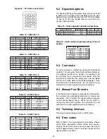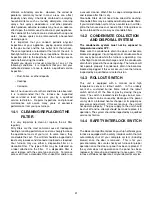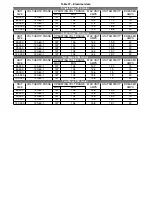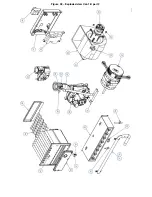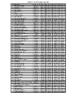
Table 23 – CFM C120-1-D/C120-2-D
MOTOR
SPEED
Static pressure
0.1
0.2
0.3
0.4
0.5
0.6
0.7
0.8
0.9
1.0
HIGH
1917 1915 1910 1830 1750 1675 1600 1520 1440 1350
MED-
HIGH
1893 1890 1885 1800 1735 1670 1600 1520 1430 1350
MED
1746 1745 1675 1605 1540 1470 1390 1335 1275 1210
LOW
1608 1600 1555 1500 1445 1390 1350 1310 1250 1210
10.2
Dipswitch options
Please refer to section 9.2.
10.3
Cool mode
Please refer to section 9.3.
10.4
Manual fan ON mode
Please refer to section 9.4.
10.5
Twinning Interface
Twinning furnaces is NOT recommended.
10.6
Error codes
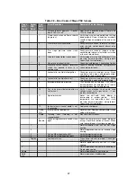
Please refer to section 9.6 and table 17.
11
2 STAGE PSC MOTOR
11.1
Selecting the blower speed
Furnaces with model number CXX-2-D are equipped
with a multi-speed circulator blower.
This blower
provides ease in adjusting blower speeds. The heating
blower speed are shipped with the suggested fan speed
describe in Table 24. These blower speeds are set for
a temperature rise of 55°F at normal static pressure.
Blowers should be adjusted by the installer to match
the installation requirements so as to provide the correct
heating temperature rise and cooling load. To adjust the
circulator blower speed, proceed as follow:
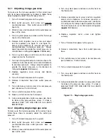
1. Turn off the power to the furnace
2. Select the heating and cooling blower speeds that
match the installation requirements from the airflow
tables in annexe.
3. Relocate the desired motor leads to the desire
speed on the motor. The red wire locate the 2nd
stage heating speed, the black wire locate the 1st
stage heating and the blue wire locate de cooling
speed.
4. If heating and cooling speeds are the same, a
jumper wire must be used between the heat and
cool terminal on the control board. The unused
leads must be connected to the “PARK” terminal on
the control board.
5. Turn on power to the furnace.
6. Verify
proper
temperature
rise.
Excessive
temperature rise can cause limit switch tripping.
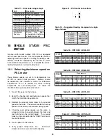
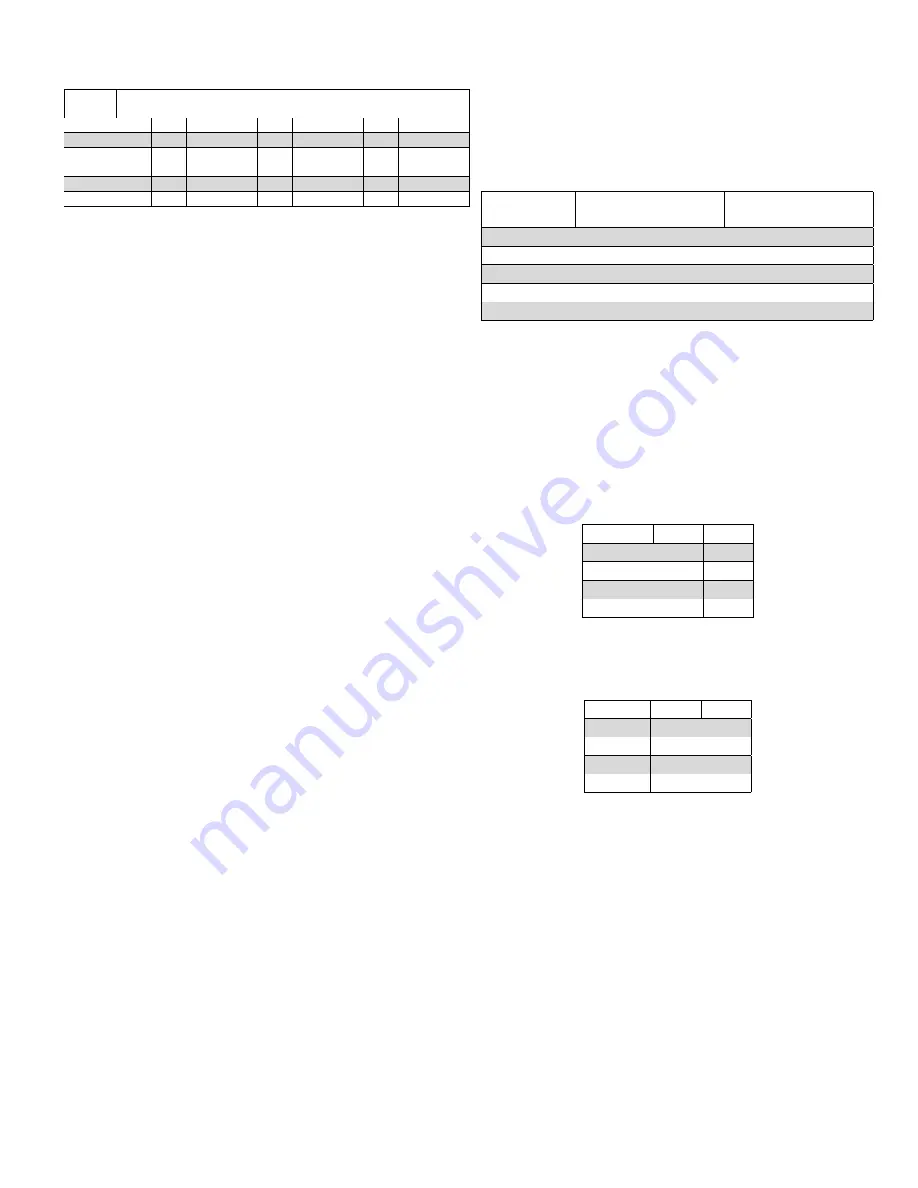
Table 24 – Suggested heating fan speed on 2 stage
furnace
INPUT
BTU/hr
HEATING
1ST
STAGE
HEATING
2ND
STAGE
45 000
LOW
MED-LOW
60 000
LOW
MED-LOW
75 000
LOW
MED-LOW
105 000
LOW
MED-HIGH
120 000
MED-LOW
HIGH
11.2
Dipswitch options
Dipswitches are used to determine :
1. Delay-to-fan-off periods. Refer to table 25
2. Second stage delay when using a single stage
thermostat. Refer to table 26
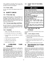
Table 25 – Heat delay-to-fan-off
DELAY
S1-3
S1-4
90 sec
OFF
OFF
120 sec
OFF
ON
150 sec
ON
OFF
180 sec
ON
ON
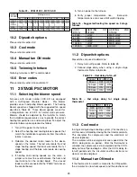
Table 26 – 2nd stage delay for single stage
thermostat
DELAY
S1-1
S1-2
OFF
OFF
OFF
10 min
ON
OFF
Auto
OFF
ON
20 min
ON
ON
11.3
Cool mode
In a typical single stage cooling system (Y connection), a
call for cool is initiated by closing the thermostat contacts.
This energizes the compressor and the electronic air
cleaner (optional).
The circulator will be energized at cool speed after the
COOL delay-to-fan-on period.
After the thermostat is
satisfied, the compressor is de-energized and the COOL
delay-to-fan-off period begins. After the COOL delay-to-
fan-off period ends, the circulator and the electronic air
cleaner are de-energized.
11.4
Manual fan ON mode
If the thermostat fan switch is moved to the ON position,
the circulator fan (low heat speed) and the electronic air
29
Содержание C105-1-D
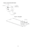
Страница 24: ...Figure 26 Alternate horizontal termination C Figure 27 Venting gasket 23...
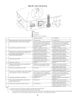
Страница 25: ...Figure 28 Direct vent clearance 24...
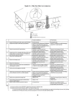
Страница 26: ...Figure 29 Other than Direct vent clearance 25...
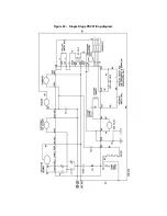
Страница 34: ...Figure 32 Single Stage PSC Wiring diagram...
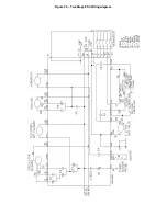
Страница 35: ...Figure 33 Two Stage PSC Wiring diagram...
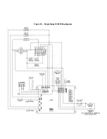
Страница 36: ...Figure 34 Single Stage ECM Wiring diagram...
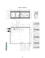
Страница 39: ...Figure 35 Dimensions 38...
Страница 40: ...Figure 36 Exploded view CXX 1 X part 1...
Страница 41: ...Figure 37 Exploded view CXX 1 X part 2...
Страница 43: ...Figure 38 Exploded view Cxx 1 D part 1...
Страница 44: ...Figure 39 Exploded view Cxx 1 D part 2...
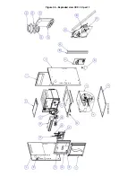
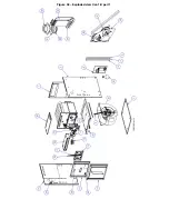
Страница 46: ...Figure 40 Exploded view Cxx 2 D part 1...
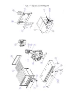
Страница 47: ...Figure 41 Exploded view Cxx 2 D part 2...

