3.4.1
Horizontal left condensate drain trap
connection
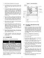
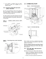
REFER TO FIGURE 10 FOR INSTALLATION DETAILS.
1. Remove all tubing from the ID blower, condensate
box and vent collector and block the stub openings
with furnished 5/8” and 1/2” black caps.
2. Remove the oblong knock-out from the bottom
middle side of the casing.
(An alternate knock-
out is available on the furnace top panel if space
is constraint)
3. Place gasket on the drain trap.
4. Screw in place the drain trap with 2 self-tapping
screws to the side of the furnace. The drain trap
must be vertical.
5. Drill open the new bottom stub of the ID blower (if
not already open). Be sure to remove all debris.
6. Reroute the ID blower drain tube from the bottom
of the ID blower casing to one of the 1/2” stub of
the drain trap. Cut the provided 1/2" tubing at the
appropriate length to reach the drain trap.
7. Reroute the condensate box drain tubing from the
bottom of the condensate box to the 5/8” stub of
the drain trap.
Cut the provided 5/8" tubing at
appropriate length to reach the drain trap.
8. Reroute the vent collector drain tube to one of the
1/2” stubs of the drain trap. Cut the provided 1/2"
tubing at the appropriate length to reach the drain
trap.
9. Connect the outlet from the drain trap to the
condensate drain piping using a ½” PVC tee. If a
condensate pump is used, make sure it is approved
for acidic condensate.
10. Prime the drain trap with water. This will ensure
proper furnace drainage at startup and will avoid
any recirculation of flue gas.
11. On the remaining 3 outlet stub, connect caps
(1x5/8” and 2x1/2”). These caps are provided in
the parts bag.
3.4.2
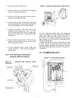
Alternate drain trap location in
horizontal left position
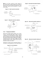
Figure 11 – Drain trap alternate position
3.4.3
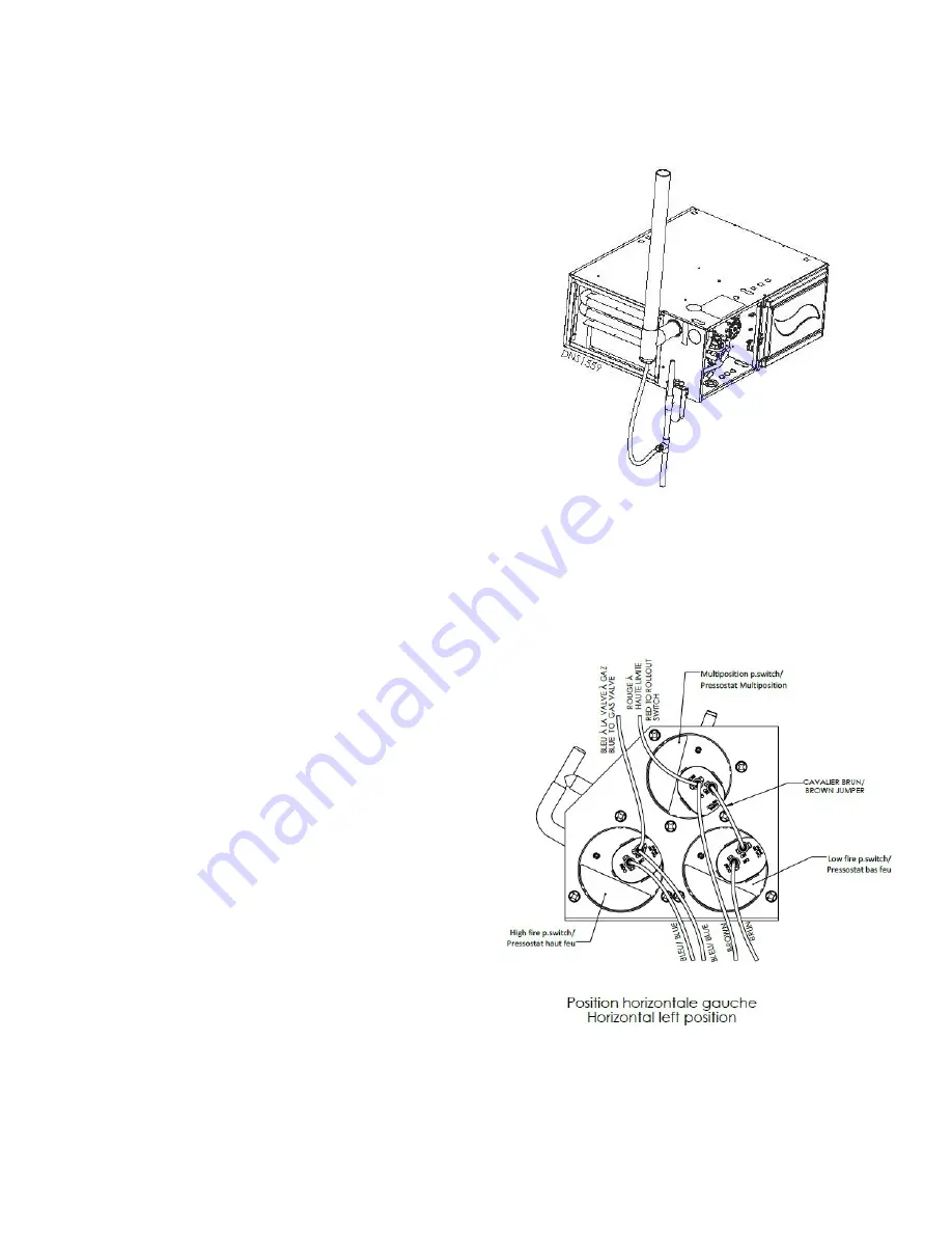
Horizontal left multiposition
pressure switch connection
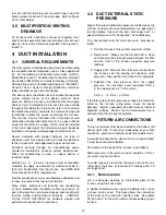
Figure 12 –
Horizontal left pressure switch
connection
The 3/16" stub just beside the drain of the condensate
box must be drilled or cut open. Use the supplied black
squared PVC tubing to connect the pressure switch (-0.2
in. w.c.) to this stub. (see figure 10)
The pressure switch must also be electrically connected
12
Содержание C105-1-D
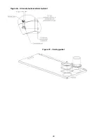
Страница 24: ...Figure 26 Alternate horizontal termination C Figure 27 Venting gasket 23...
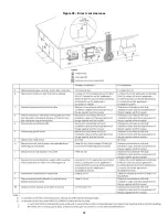
Страница 25: ...Figure 28 Direct vent clearance 24...
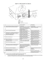
Страница 26: ...Figure 29 Other than Direct vent clearance 25...
Страница 34: ...Figure 32 Single Stage PSC Wiring diagram...
Страница 35: ...Figure 33 Two Stage PSC Wiring diagram...
Страница 36: ...Figure 34 Single Stage ECM Wiring diagram...
Страница 39: ...Figure 35 Dimensions 38...
Страница 40: ...Figure 36 Exploded view CXX 1 X part 1...
Страница 41: ...Figure 37 Exploded view CXX 1 X part 2...
Страница 43: ...Figure 38 Exploded view Cxx 1 D part 1...
Страница 44: ...Figure 39 Exploded view Cxx 1 D part 2...
Страница 46: ...Figure 40 Exploded view Cxx 2 D part 1...
Страница 47: ...Figure 41 Exploded view Cxx 2 D part 2...


