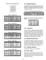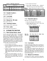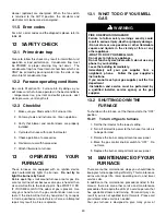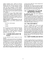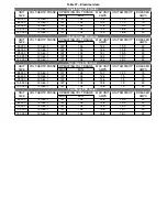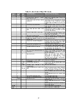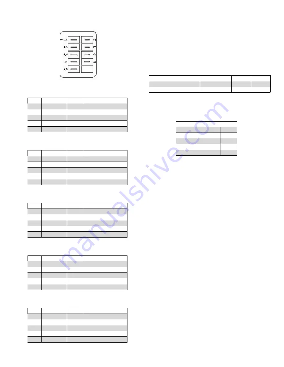
Figure 30 – X13 motor connections
Table 10 – CFM C45-1-X
TAP
TORQUE
CFM
DESCRIPTION
5
100
1210
3 T.
4
72
1015
2.5 T.
3
50
780
dT=55°F
2
40
610
1.5 T.
1
33
490
CONSTANT CIRC.
Table 11 – CFM C60-1-X
TAP
TORQUE
CFM
DESCRIPTION
5
100
1350
3.5 T.
4
85
1200
3 T.
3
75
1090
dT=55°F
2
50
830
2 T.
1
35
560
CONSTANT CIRC.
Table 12 – CFM C75-1-X
TAP
TORQUE
CFM
DESCRIPTION
5
100
1545
4 T.
4
85
1440
3.5 T.
3
70
1265
dT=55°F
2
37
810
2 T.
1
25
560
CONSTANT CIRC.
Table 13 – CFM C105-1-X
TAP
TORQUE
CFM
DESCRIPTION
5
95
1800
4.5 T.
4
87
1735
dT=55°F
3
78
1600
4 T.
2
63
1400
3.5 T.
1
30
800
CONSTANT CIRC.
Table 14 – CFM C120-1-X
TAP
TORQUE
CFM
DESCRIPTION
5
100
1910
dT=55°F
4
92
1797
4.5 T.
3
73
1601
4 T.
2
60
1404
3.5 T.
1
28
801
CONSTANT CIRC.
9.2
Dipswitch options
The option switches on the single stage furnace are used
to determine the length of the cool delay-to-fan-off, heat
delay-to-fan-on and heat delay-to-fan-off. Refer to tables
15 and 16 for the time period that will result from the
various switch positions.
Table 15 – Option dipswitch position single stage
DESCRIPTION
DIPSWITCH
ON
OFF
COOL delay-to-fan-off
S1
45 sec
90 sec
HEAT delay-to-fan-on
S2
30 sec
45 sec
Table 16 – Option switch single stage delay to fan off
heating
HEAT delay
DIPSWITCH
to-fan-off
S3
S4
60 sec
ON
ON
90 sec
OFF
ON
120 sec
ON
OFF
180 sec
OFF
OFF
9.3
Cool mode
A call for cooling is initiated by closing the thermostat
contacts. This energizes the control and the compressor.
The optional electronic air cleaner is energized, and
the circulator fan is energized at cool speed. After the
thermostat is satisfied, the compressor is de-energized
and the cool mode delay-to-fan-off period begins. After
the delay-to-fan off period ends, the circulator fan and
electronic air cleaner (optional) are de-energized.
9.4
Manual Fan ON mode
If the thermostat fan option is moved to the ON position,
the circulator fan and optional electronic air cleaner are
energized.
The circulator fan speed will be energyze
at the cooling speed chosen. When the fan switch is
returned to the AUTO position, the circulator fan and
electronic air cleaner (optional) are de-energized.
9.5
Twinning Interface
Twinning should not happen with an ECM motor.
9.6
Error codes
Refer to table 17 for a description of error codes. Please
check those description before calling tech service.
Anyway, the tech will ask for your error code. Each flash
will last approximately 0.25 sec and each pause will last
approximately 2 seconds.
27
Содержание C105-1-D
Страница 24: ...Figure 26 Alternate horizontal termination C Figure 27 Venting gasket 23...
Страница 25: ...Figure 28 Direct vent clearance 24...
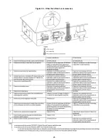
Страница 26: ...Figure 29 Other than Direct vent clearance 25...
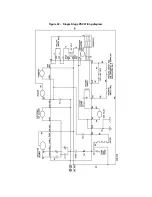
Страница 34: ...Figure 32 Single Stage PSC Wiring diagram...
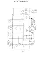
Страница 35: ...Figure 33 Two Stage PSC Wiring diagram...
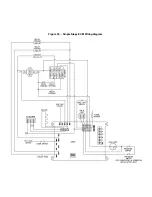
Страница 36: ...Figure 34 Single Stage ECM Wiring diagram...
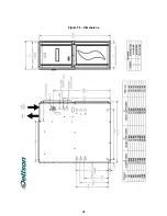
Страница 39: ...Figure 35 Dimensions 38...
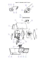
Страница 40: ...Figure 36 Exploded view CXX 1 X part 1...
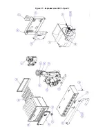
Страница 41: ...Figure 37 Exploded view CXX 1 X part 2...
Страница 43: ...Figure 38 Exploded view Cxx 1 D part 1...
Страница 44: ...Figure 39 Exploded view Cxx 1 D part 2...
Страница 46: ...Figure 40 Exploded view Cxx 2 D part 1...
Страница 47: ...Figure 41 Exploded view Cxx 2 D part 2...

