background image

NOTE

: Do not allow insulation or other materials to

accumulate inside the pipe assembly when installing it
through the hole. Disassemble loose pipe fittings. Clean
and cement using the same procedures as used for
system piping.

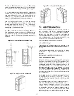
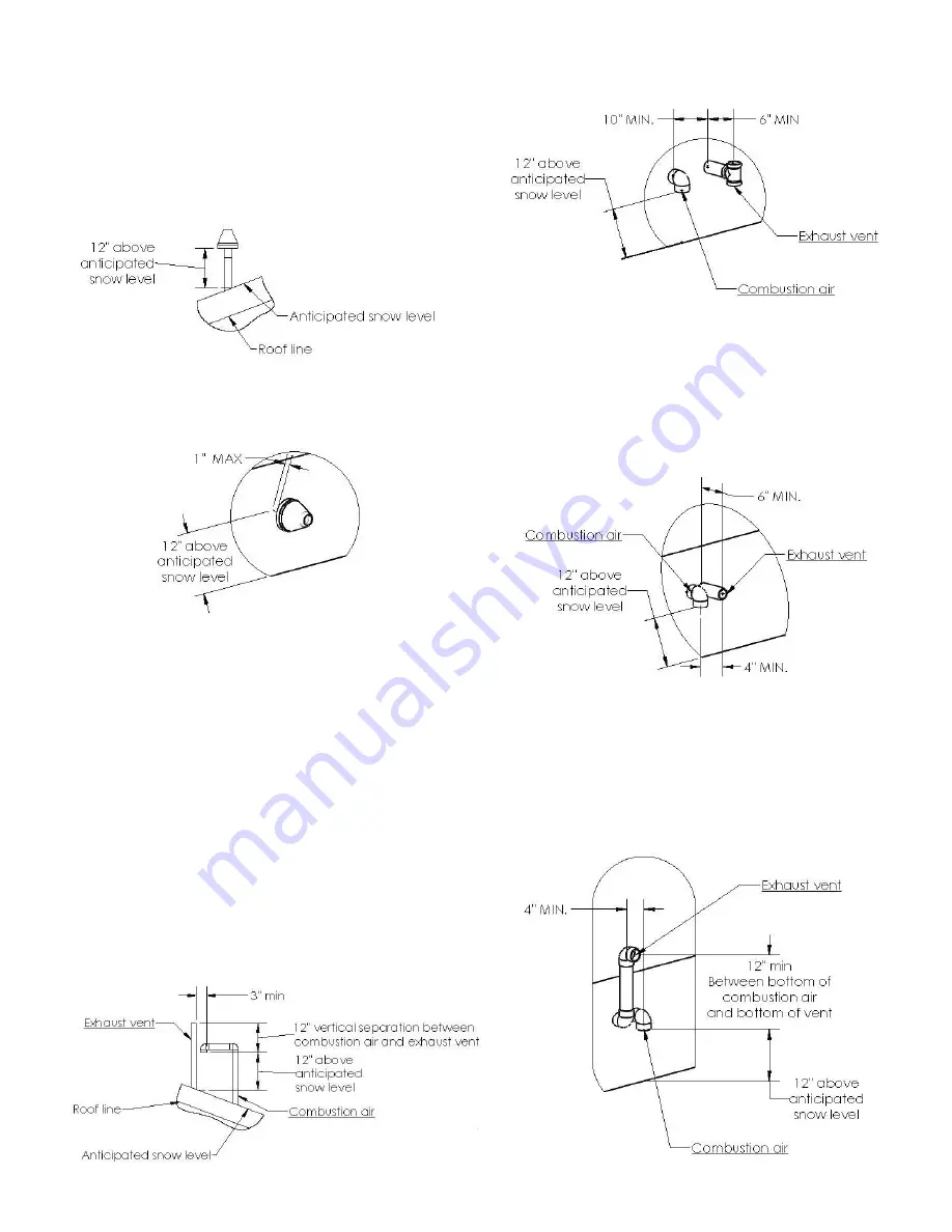
Figure 20 – Roof concentric termination

Figure 21 – Sidewall concentric termination

7.9.2

Two pipe termination

Maintain the required distance between vents or pairs
of vents. Cut the required number of holes in the roof
or sidewall for vent and combustion air pipes. Sidewall
holes for two pipes vent terminations should be side-by-
side, allowing space between the pipes for the elbows to
fit on the pipes. Holes in the roof for two pipe terminations
should be spaced no more than 18” (457 mm) apart.
Termination elbows will be installed after the vent and
combustion air pipe are installed.

Combustion air intake can be snorkeled to acheive 12"
min distance from expected level of snow and/or ground.

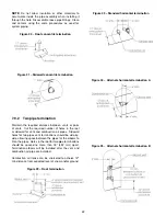
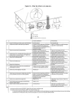
Figure 22 – Roof termination

Figure 23 – Standard horizontal termination

Figure 24 – Alternate horizontal termination A

Figure 25 – Alternate horizontal termination B

22

Содержание C105-1-D

Страница 1: ...old in US and Canada INSTALLER SERVICE TECHNICIAN Use the information in this manual for the installation servicing of the furnace and keep the document near the unit for future reference HOMEOWNER Pl...

Страница 2: ...MET 14 5 4 SETTING GAS OUTLET PRESSURE 14 5 4 1 Adjusting 2 stage gas valve 15 5 4 2 Adjusting single stage gas valve 15 6 ELECTRICAL CONNECTIONS 17 6 1 120V WIRING 17 6 2 24V WIRING 17 6 3 FUSE 17 6...

Страница 3: ...Stage PSC Wiring diagram 33 Figure 33 Two Stage PSC Wiring diagram 34 Figure 34 Single Stage ECM Wiring diagram 35 Figure 35 Dimensions 38 Figure 36 Exploded view CXX 1 X part 1 39 Figure 37 Exploded...

Страница 4: ...assess the damage and to replace all critical parts that were in contact with water 3 Do not store gasoline or any other flammable substances such as paper or carton near the furnace 4 Do not stack it...

Страница 5: ...o be handled by duct s sealed to the furnace casing and terminating outside the space containing the furnace See section 4 DUCT INSTALLATION This furnace may be installed with a two pipe sealed combus...

Страница 6: ...th the National Fuel Gas Code ANSI Z223 1 NFPA 54 and or Natural Gas and Propane Installation code CSA B149 1 9 After it has been determined that each appliance connected to the venting system properl...

Страница 7: ...ng Systems ANSI NFPA 90B National Standard of Canada Natural Gas and Propane Installation Code NSCNGPIC CAN CSA B149 1 General installation NFGC and the NFPA 90B For copies contact the National Fire P...

Страница 8: ...water Not be installed directly on any combustible material other than wood flooring Be located close to the chimney or vent and attached to an air distribution system Refer to section 7 Place the un...

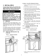
Страница 9: ...r slightly leaned forward to help drain condensate 3 1 1 Right side condensate drain trap connection Figure 1 Right side connection See figure 1 and read the following instructions 1 Remove the oblong...

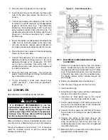
Страница 10: ...supply duct going through the floor and the proper slope of the furnace for condensate drainage Also the base allows sufficient spacing for the venting and the drain trap When installing the furnace...

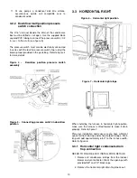
Страница 11: ...ssure switch assembly Figure 5 Connecting pressure switch in downflow position 3 3 HORIZONTAL RIGHT Figure 6 Horizontal right position Figure 7 Horizontal right slope When installing the furnace in ho...

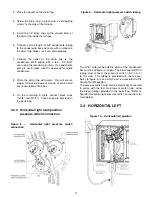
Страница 12: ...on of flue gas 9 On the remaining 5 inlets connect black caps 1x5 8 and 2x1 2 These caps are provided in the parts bag 3 3 2 Horizontal right multiposition pressure switch connection Figure 8 Horizont...

Страница 13: ...ub of the drain trap Cut the provided 5 8 tubing at appropriate length to reach the drain trap 8 Reroute the vent collector drain tube to one of the 1 2 stubs of the drain trap Cut the provided 1 2 tu...

Страница 14: ...n of vibration Many states provinces and localities are considering or have implemented standards and or restrictions on duct sizing practices ductwork leakage and or ductwork thermal airflow and elec...

Страница 15: ...d local codes Refer to current edition of NFGC in the U S A Refer to current edition of CAN CSA B149 1 in Canada Installations must be made in accordance with all authorities having jurisdiction Use a...

Страница 16: ...wise 7in lb minimum 12 Turn on electrical power to the system 13 Make a call for heat on the thermostat 14 Using a leak detection solution or soap suds check for leaks at the pressure boss screw If a...

Страница 17: ...l Gas Propane High fire 100 3 0 8 6 Low fire 70 1 55 5 0 Figure 16 Typical gas pipe arrangement Table 6 Maximum capacity of pipe Cu ft Hr for pipe length ft m Nominal Iron pipe size in mm Internal dia...

Страница 18: ...r cooling operation Use only AWG No 18 color coded copper thermostat wire Use AWG No 18 color coded copper thermostat wire for lengths up to 100ft 30 5m For wire lengths over 100 ft use AWG No 16 wire...

Страница 19: ...1 4 per foot of run so that condensate drains toward the furnace Support horizontal vent piping at least every five feet No sags or dips are permitted The vent pipe and combustion air pipe must termin...

Страница 20: ...nt pipe installations in Canada must conform to the requirements of CAN CSA B149 code PVC and CPVC vent systems must be composed of pipe fittings cements and primers listed to ULC S636 and must be of...

Страница 21: ...distribution of primer and cement 8 Clean and dry all surfaces to be joined 9 Check dry fit of the pipe and mark insertion depth on the pipe 10 After the pipes have been cut and preassembled apply a...

Страница 22: ...allation codes and the requirements of the gas supplier and the instructions in this manual A vent for this appliance shall not terminate over public walkways near soffit vents or crawl space vents or...

Страница 23: ...of or sidewall for vent and combustion air pipes Sidewall holes for two pipes vent terminations should be side by side allowing space between the pipes for the elbows to fit on the pipes Holes in the...

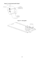
Страница 24: ...Figure 26 Alternate horizontal termination C Figure 27 Venting gasket 23...

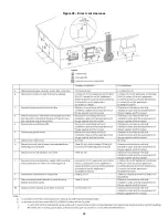
Страница 25: ...Figure 28 Direct vent clearance 24...

Страница 26: ...Figure 29 Other than Direct vent clearance 25...

Страница 27: ...light the main burners 3 Set the thermostat to it lowest setting and turn off furnace electrical power 4 Replace the burner compartment control access door WARNING Failure to replace the burner door c...

Страница 28: ...fan on S2 30 sec 45 sec Table 16 Option switch single stage delay to fan off heating HEAT delay DIPSWITCH to fan off S3 S4 60 sec ON ON 90 sec OFF ON 120 sec ON OFF 180 sec OFF OFF 9 3 Cool mode A cal...

Страница 29: ...minal on the control board The unused leads must be connected to the PARK terminal on the control board 5 Turn on power to the furnace 6 Verify proper temperature rise Excessive temperature can cause...

Страница 30: ...cate the 1st stage heating and the blue wire locate de cooling speed 4 If heating and cooling speeds are the same a jumper wire must be used between the heat and cool terminal on the control board The...

Страница 31: ...air it Call a qualified service technician Force or attempted repair may result in a fire or explosion 13 1 WHAT TO DO IF YOU SMELL GAS WARNING FIRE OR EXPLOSION HAZARD Failure to follow safety warnin...

Страница 32: ...excess dirt from a cleanable filter shake filter and or use a vacuum cleaner Wash filter in soap or detergent water and replace after filter is dry Cleanable filters do not need to be oiled after was...

Страница 33: ...5 9 20 75 000 120 60 1 127 104 13 1 15 5 20 105 000 120 60 1 127 104 16 4 19 7 20 120 000 120 60 1 127 104 16 4 19 7 20 Two Stage ECM motor UNIT VOLT HERTZ PHASE OPERATING VOLT RANGE MAX UNIT UNIT AMP...

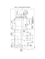
Страница 34: ...Figure 32 Single Stage PSC Wiring diagram...

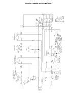
Страница 35: ...Figure 33 Two Stage PSC Wiring diagram...

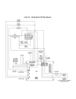
Страница 36: ...Figure 34 Single Stage ECM Wiring diagram...

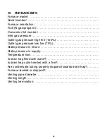
Страница 37: ...essure high fire 100 Outlet gas pressure low fire 70 Static pressure in return Static pressure in supply Temperature rise Is drain trap filled with water Is drain trap outlet vented with a Tee Are con...

Страница 38: ...ve Make sure flame rod is clean and properly wired 9 Improper grounding or polarity 120V hot and neutral reversed 120V should be read between Hot and ground 0V should be read between Neutral and groun...

Страница 39: ...Figure 35 Dimensions 38...

Страница 40: ...Figure 36 Exploded view CXX 1 X part 1...

Страница 41: ...Figure 37 Exploded view CXX 1 X part 2...

Страница 42: ...7 26 B30157 26 B30157 26 B30157 26 30 Ignitor R03K005K R03K005K R03K005K R03K005K R03K005K 31 Roll out switch R02N022 R02N022 R02N022 R02N022 R02N022 32 Gas manifold orifice included B40527 B40528 B40...

Страница 43: ...Figure 38 Exploded view Cxx 1 D part 1...

Страница 44: ...Figure 39 Exploded view Cxx 1 D part 2...

Страница 45: ...B40903 B40903 B40903 B40903 B40903 31 Venting flange gasket B40567 B40567 B40567 B40567 B40567 32 Drain trap B40760 B40760 B40760 B40760 B40760 33 Venting flange B40533 B40533 B40533 B40533 B40533 34...

Страница 46: ...Figure 40 Exploded view Cxx 2 D part 1...

Страница 47: ...Figure 41 Exploded view Cxx 2 D part 2...

Страница 48: ...ng gasket B40903 B40903 B40903 B40903 B40903 33 Venting flange gasket B40567 B40567 B40567 B40567 B40567 34 Drain trap B40760 B40760 B40760 B40760 B40760 35 Venting flange B40533 B40533 B40533 B40533...

Отзывы: