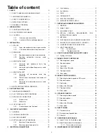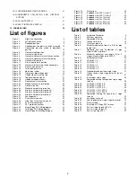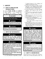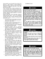
5.4.1
Adjusting 2 stage gas valve
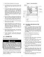
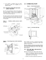
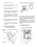
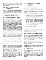
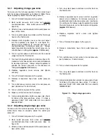
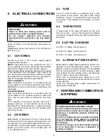
To make sure the furnace operates to the correct input
refer to furnace rating plate or to table 5, follow those
steps to properly adjust the outlet gas pressure:
1. Turn off all electrical power to the system.
2. Back outlet pressure test screw out one turn
counterclockwise.
(See outlet pressure boss on
figure 14)
3. Attach a hose and manometer to the oulet pressure
boss of the valve.
4. Turn on system power and make a call for first stage
heat on the thermostat.
5. Remove both regulator cover screw and adjust
low fire regulator (see figure 14 and figure 15).
Adjust screw clockwise to increase pressure or
counterclockwise to decrease pressure.
Always
adjust regulator to provide the correct pressure, as
mentionned on rating plate
(approx. 1.55 in w.c.)
.
6. Turn on system power and make a call for second
stage heat on the thermostat.
7. Turn high fire regulator adjust screw (see figure 14)
clockwise to increase pressure or counterclockwise
to decrease pressure. Always adjust regulator to
provide the correct pressure, as mentionned on
rating plate
(approx. 3.0 in w.c.)
.
8. Replace regulators cover screws and tighten
securely.
9. Turn off all electrical power to the system.
10. Remove manometer hose from outlet pressure
boss.
11. Turn outlet pressure test screw in to seal pressure
port (clockwise, 7in-lb minimum)
12. Turn on electrical power to the system.
13. Make a call for heat on the thermostat.
14. Using a leak detection solution or soap suds, check
for leaks at the pressure boss screw. If a leak is
detected, SHUT OFF GAS AND FIX ALL LEAKS
IMMEDIATELY.
5.4.2
Adjusting single stage gas valve
To make sure the furnace operates to the correct input,
follow those steps to properly adjust the outlet gas
pressure:
1. Turn off all electrical power to the system.
2. Back outlet pressure test screw out one turn
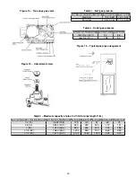
counterclockwise.(See outlet pressure boss on
figure 13)
3. Attach a hose and manometer to the oulet pressure
boss of the valve.
4. Turn on system power and make a call for heat on
the thermostat.
5. Remove regulator cover screw and turn regulator
adjust screw clockwise to increase pressure or
counterclockwise to decrease pressure. (see figure
13 and figure 15) Always adjust regulator to provide
the correct pressure, as mentionned on rating plate
(approx. 3.0 in w.c.)
.
6. Replace
regulator
cover
screw
and
tighten
securely.
7. Turn off all electrical power to the system.
8. Remove manometer hose from outlet pressure
boss.
9. Turn outlet pressure test screw in to seal pressure
port (clockwise, 7in-lb minimum)
10. Turn on electrical power to the system.
11. Turn on system power and make a call for heat on
the thermostat.
12. Using a leak detection solution or soap suds, check
for leaks at the pressure boss screw. If a leak is
detected, SHUT OFF GAS AND FIX ALL LEAKS
IMMEDIATELY.
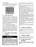
Figure 13 – Single stage gas valve
15
Содержание C105-1-D
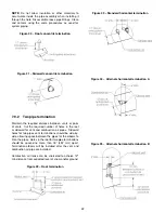
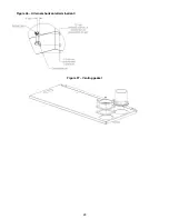
Страница 24: ...Figure 26 Alternate horizontal termination C Figure 27 Venting gasket 23...
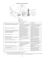
Страница 25: ...Figure 28 Direct vent clearance 24...
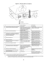
Страница 26: ...Figure 29 Other than Direct vent clearance 25...
Страница 34: ...Figure 32 Single Stage PSC Wiring diagram...
Страница 35: ...Figure 33 Two Stage PSC Wiring diagram...
Страница 36: ...Figure 34 Single Stage ECM Wiring diagram...
Страница 39: ...Figure 35 Dimensions 38...
Страница 40: ...Figure 36 Exploded view CXX 1 X part 1...
Страница 41: ...Figure 37 Exploded view CXX 1 X part 2...
Страница 43: ...Figure 38 Exploded view Cxx 1 D part 1...
Страница 44: ...Figure 39 Exploded view Cxx 1 D part 2...
Страница 46: ...Figure 40 Exploded view Cxx 2 D part 1...
Страница 47: ...Figure 41 Exploded view Cxx 2 D part 2...

