DDFP
SECTION 3.6
Page 45
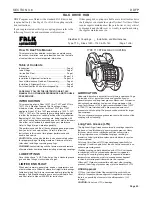
PARTS IDENTIFICATION
All coupling parts have identifying part numbers as shown
below. Parts 3 and 4 (Hubs and Grids), are the same for both
Type T10 and T20 couplings. All other coupling parts are unique to
Type T10. When ordering parts, always SPECIFY SIZE and TYPE
shown on the COVER.
PARTS INTERCHANGEABILITY
Parts are interchangeable between Sizes 20T and 1020T, 30T
and 1030T, etc. except as noted.
GRIDS — Size 1020T thru 1140T Steelflex couplings use blue
grids. Older models, 20T thru 140T, use orange grids.
CAUTION:
Blue grids may be used in all applications, but DO
NOT substitute orange grids for blue.
COVERS —
CAUTION:
DO NOT mix cover halves of different
designs. Sizes 1020T thru 1070T10 covers have been
manufactured in several different two-rib designs and 80T thru
140T covers have been manufactured with two and three ribs.
HARDWARE ó Older style covers, Sizes 1020T10 thru
1070T10, utilized socket head cap screws with captured
locknuts. The new style covers use hex head cap screws (either
inch or metric) and unrestrained locknuts. Specify either inch
series SOCKET head or inch or metric series HEX head cap
screws when ordering replacement parts.
PART NUMBERS
1. Seal (T10)
2. Cover (T10)
3. Hub (Specify bore
and keyway)
4. Grid
5. Gasket (T10)
6. Fasteners (T10) ó Coupling
may be supplied with one
set each of inch series fas-
teners and metric fasteners.
7. Lube Plug
SIZE &
PART
NUMBER
ORDER INFORMATION
1. Identify part(s) required by
name above.
2. Furnish the following
information.
EXAMPLE:
Coupling Size: 1030
Coupling Type: T10
Model: B
Bore: 1.375
Keyway: .375 x .187
3. Price parts from Price List
422-110 and appropriate
discount sheet.
PART NUMBER LOCATION
(1.) SEAL
(3.) HUB
SIZE
PART NUMBER
(4.) GRID
(2.) COVER
(6.)
1030
T
10
B
(5.) GASKET
(7.)
PART NUMBER
COUPLING
SIZE
TYPE
MODEL
PRODUCT
CLASSIFICATION
SIZE
SIZE, PART NUMBER &
BORE
(Page 6 of 6)
Steelflex ® Couplings
•
•
Installation and Maintenance
Type T10
Sizes 1020 –1140 & 20–140
®
a good name in industry
Содержание DDFP Series
Страница 13: ...DDFP SECTION 2 Front View V 71 Page 9 A Front View I 71 Right Side View I 71 Right Side View 6V 71 ...
Страница 14: ...Page 9 B SECTION 2 DDFP Front View 12V 92 Left Side View 12V 92 Front View V 92 Right Side View V 92 ...
Страница 22: ...SECTION 3 2 DDFP AIR FILTER SERVICE INSTRUCTIONS Figure 1 Air Filter Service Instructions Page 17 ...
Страница 42: ...SECTION 3 5 DDFP Page 37 Fig 13 DC Wiring Diagram Engines With Mechanical Guages ...
Страница 43: ...DDFP Fig 14 DC Wiring Diagram Engines With Electrical Guages Page 38 SECTION 3 5 ...
Страница 44: ...SECTION 3 5 DDFP Page 39 Fig 15 AC Wiring Diagram ...

