DDFP
SECTION 3.5
Page 34
overspeed condition. The reset b utton is sho wn in Fig. 8,
Page 33.
NOTE:
Engine will not r estart after an o verspeed shut-
down, UNTIL OPERA TOR RESETS THIS
BUTTON. DO NO T ATTEMPT TO RESTART
ENGINE UNTIL VERIFICATION HAS BEEN
MADE AS TO THE REASON FOR O VER-
SPEED.
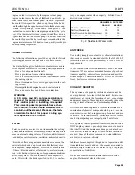
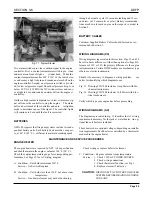
A magnetic-pic kup, mounted in the f lywheel housing pr o-
vides the input signal f or the o verspeed switch. See Fig. 9,
pickup mounting. The magnetic-pickup senses the speed of
the engine by counting the f lywheel ring gear teeth per sec -
ond. There should be a 0.03" (.762 MM) air gap between the
top of the r ing gear and the ma gnetic pickup. With a gear
tooth aligned with the center of the ma gnetic pic kup hole,
thread the pickup in until it touc hes the gear tooth and then
back it out
1/
2
turn. Tighten jam nut while holding the
pickup in position. Reconnect to wiring harness.
WARNING:
All current production DDFP engines use
electronic o verspeed protection controls. Due
to the delicate nature of this devise, it is manda-
tory that diagnostic probing of the circuitry be
done with the electrical po wer of f. Probing
with any device that causes amperage to exceed
ratings will damage this control. This warning
applies to terminals of the o verspeed switch
and inside the junction box. This type of failure
is not warrantable.
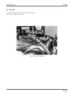
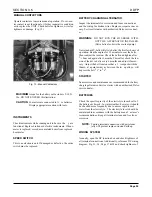
BATTERY CHARGING ALTERNATOR
This belt dri ven engine alternator pro vides po wer to
recharge both battery banks directly through the battery iso-
lator. The battery isolator pre vents backfeed from one bat-
tery bank to the other. The alternator is mounted at the front
of the engine as shown in Fig. 10. The alternator is belt dri-
ven from the crankshaft or camshaft pulle y.
STARTER
Fig. 9 - Magnetic Pickup
Fig. 10 - Typical Alternator
The DC electric starting motor pro vides cranking ef fort to
initiate an engine start. Located on the flywheel housing of
the engine, it is shown in Fig. 11, Page 35.
For automatic operation or test operation, the signal for start
initiation comes from the controller. For manual start at the
engine, activating either contactor #1 or #2 should start the
engine. Re view the MANU AL OPERATING INSTR UC-
TIONS for additional details on Page 33.
Содержание DDFP Series
Страница 13: ...DDFP SECTION 2 Front View V 71 Page 9 A Front View I 71 Right Side View I 71 Right Side View 6V 71 ...
Страница 14: ...Page 9 B SECTION 2 DDFP Front View 12V 92 Left Side View 12V 92 Front View V 92 Right Side View V 92 ...
Страница 22: ...SECTION 3 2 DDFP AIR FILTER SERVICE INSTRUCTIONS Figure 1 Air Filter Service Instructions Page 17 ...
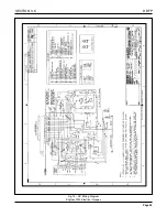
Страница 42: ...SECTION 3 5 DDFP Page 37 Fig 13 DC Wiring Diagram Engines With Mechanical Guages ...
Страница 43: ...DDFP Fig 14 DC Wiring Diagram Engines With Electrical Guages Page 38 SECTION 3 5 ...
Страница 44: ...SECTION 3 5 DDFP Page 39 Fig 15 AC Wiring Diagram ...

