


DDFP
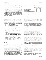
AIR BOX DRAINS
During normal engine operation,
water v apor from the
intake air, as well as a slight amount of fuel and lubricating
oil fumes, condenses and settles on the bottom of the air
box. This condensation is remo ved by the air box pressure
through air box drain tubes mounted on the side of the cylin-
der block.
SECTION 3.2
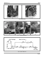
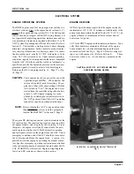
CRANKCASE VENTILATION
Harmful vapors which may form within the engine are re-
moved from the crankcase, gear train, and injector compart-
ments by a continuous, pressurized ventilation system.
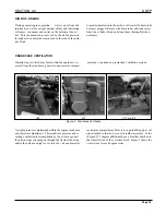
Figure 2 - Crankcase Ventilation
I-53
V71 or V-92
I-71
Liquid accumulation in the air box will result if a drain tube
becomes plugged. Remo ve the drain tubes and connectors
from the c ylinder block and clean them thoroughly when
necessary.
rocker arm compartment. Here it is e xpelled through a vent
pipe attached to the rock er cover breather assembly. Turbo
charged I-71 engines additionally use a breather attached to
the front left side of the c ylinder block. Figure 2 sho ws the
vent system for each engine series.
A slight pressure is maintained within the engine crankcase
and injector compartment. This crankcase pressure and re-
sulting ventilation is accomplished by the air seepage past
the piston rings sweeping up through the flywheel housing
and/or the balance weight co ver into the v alve and injector
Page 18
Содержание DDFP Series
Страница 13: ...DDFP SECTION 2 Front View V 71 Page 9 A Front View I 71 Right Side View I 71 Right Side View 6V 71 ...
Страница 14: ...Page 9 B SECTION 2 DDFP Front View 12V 92 Left Side View 12V 92 Front View V 92 Right Side View V 92 ...
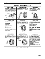
Страница 22: ...SECTION 3 2 DDFP AIR FILTER SERVICE INSTRUCTIONS Figure 1 Air Filter Service Instructions Page 17 ...
Страница 42: ...SECTION 3 5 DDFP Page 37 Fig 13 DC Wiring Diagram Engines With Mechanical Guages ...
Страница 43: ...DDFP Fig 14 DC Wiring Diagram Engines With Electrical Guages Page 38 SECTION 3 5 ...
Страница 44: ...SECTION 3 5 DDFP Page 39 Fig 15 AC Wiring Diagram ...


