SECTION 3.5
DDFP
Page 33
MANUAL START INSTRUCTIONS
The engine can be operated without using the engine con-
troller. Use the following procedure when manual starting is
required. Refer to Fig. 2, Page 32.
To Start Engine
1. OPEN COOLING SYSTEM MANU
AL BYP ASS
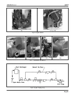
VALVE. Located on the cooling loop, Fig. 8, Page 29.
2. POSITION
MODE
SELECTOR IN
MANUAL
RUN.
Fig. 3, Page 32.
3. POSITION
BATTERY SELECTOR
SWITCH T O
BATT. #1.
4. PULL AND HOLD MANUAL CONTACTOR #1, Fig.
4, Page 32 UNTIL ENGINE ST
ARTS, RELEASE
AFTER 5 SECONDS. IF UNIT F AILS TO ST ART,
POSITION
BATTERY SELECTOR
TO B #2 USE
STARTER CONTACTOR #2, AND REPEAT STEP.
To Stop Engine
1. RETURN
MODE SELECTOR
TO
AUTOMATIC,
AND
MANUAL STOP,
ENGINE WILL STOP.
2. CLOSE COOLING SYSTEM MANU AL BY -PASS
VALVE.
IMPORTANT:
DO NOT
LEAVE THE
MODE SELECTOR
SWITCH
IN THE
MANUAL RUN
POSITION DURING
AUTO-
MATIC
OPERATION. (THE CONTROLLER WILL BE
UNABLE TO STOP THE ENGINE AND
OVERHEAT
DAMAGE WILL RESULT
)
DO NOT
POSITION THE
BATTERY SELECTOR
SWITCH TO A DEFECTIVE B ATTERY WHILE IN
THE
MANUAL MODE.
GOVERNOR OPERATING SOLENOID
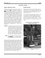
The DC go vernor solenoid, Fig. 6, Page 32, is an essential
item for the operation of this fire pump system. Upon receiv-
ing a signal, the solenoid is energized to move the governor
into the run position.
This solenoid remains ener gized during engine operation.
To stop the engine, the solenoid de-energizes and the gover-
nor returns to the "no fuel" position by spring action.
INSTRUMENTATION
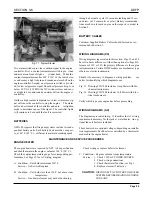
Figure 7, Page 32 sho ws the instrumentation panel which
contains the follo wing gauges: tachometer with inte gral
hourmeter (1), engine oil pressure (P.S.I.) (2), battery volt-
meter (3), engine coolant temperature (°F) (4), battery isola-
tor (5). Engine overspeed switch is mounted to rear of gauge
panel Figure 8.
Tachometer and Integral Hourmeter -
This meter re-
ceives its signal from the o verspeed switch to allo w operator
to read engine RPM, in addition the hour meter records a
cumulative total of engine operating hours.
Oil Pressure -
This mechanical gauge gives engine oil pres-
sure readings in english and metr ic units (PSI & kP A). Con-
nection location to the engine will vary per engine model.
Engine Coolant Temperature -
This temperature gauge
indicates the engines coolant outlet temper ature in de grees
fahrenheit (°F) and centrigrade (°C).
Voltmeter -
This gauge identifies the voltage level of the bat-
tery according to the position of the ba ttery selector switch.
SPEED SWITCH
After the engine has started and reached 1000 RPM,the speed
switch signals the contr oller to terminate the starter cranking
action. An overrunning clutch is included on the star ter drive
to prevent damage from overspeeding when the unit starts.
NOTE:
When starting unit with man ual contactor s, re-
lease contactor handle as soon as eng ine starts.
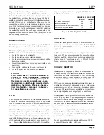
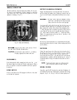
In the event of an engine o verspeed the speed s witch signals
the AEC and ef fects an engine shutdo wn. A MANU AL
RESET button is included on the switch and must be "pushed
in" to reset the speed s witch after unit has shutdo wn from an
Fig. 8 - Overspeed Reset
➞
➞
Содержание DDFP Series
Страница 13: ...DDFP SECTION 2 Front View V 71 Page 9 A Front View I 71 Right Side View I 71 Right Side View 6V 71 ...
Страница 14: ...Page 9 B SECTION 2 DDFP Front View 12V 92 Left Side View 12V 92 Front View V 92 Right Side View V 92 ...
Страница 22: ...SECTION 3 2 DDFP AIR FILTER SERVICE INSTRUCTIONS Figure 1 Air Filter Service Instructions Page 17 ...
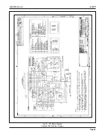
Страница 42: ...SECTION 3 5 DDFP Page 37 Fig 13 DC Wiring Diagram Engines With Mechanical Guages ...
Страница 43: ...DDFP Fig 14 DC Wiring Diagram Engines With Electrical Guages Page 38 SECTION 3 5 ...
Страница 44: ...SECTION 3 5 DDFP Page 39 Fig 15 AC Wiring Diagram ...


