


**Based On Nominal System. Flow Analysis Must Be Done To Assure Adherance To System Limitations.
(Minimum Exhaust Pipe Diameter is based on 15 feet of pipe, one elbow, and a silencer
pressure drop no greater than one half the max. allowable back pressure.)
***Review For Power Deration If Air Entering Engine Exceeds 77˚ F (25˚ C).
53.2 (201) 53.9 (204)
65 (448)
3.2 (12.1)
68 (469)
3.9 (14.8)
40 (10.1)
40 (10.1)
Exhaust Flow - ft.3/min. (m3/min.)............................................
576 (16)
646 (18)
710 (20)
762 (22)
818 (23)
Exhaust Temperature - ˚F (˚C)....................................................
840 (449) 840 (449)
845 (452) 855 (457) 860 (460)
Maximum Allowable Back Pressure -
in. H2O (kPa) ........................................................................
40 (10.1)
40 (10.1)
40 (10.1)
40 (10.1) 40 (10.1)
Min. Exhaust Pipe Dia.-in. (mm)** ..........................................
Fuel System
Fuel Pressure - lb./in.2 (kPa) ....................................................
70 (482)
72 (496)
74 (510)
75 (517)
76 (524)
Fuel Consumption - gal./hr. (L/hr.) ............................................
4.8 (18.2)
5.3 (20.0) 5.5 (20.8) 5.9 (22.3) 6.1 (23.1)
Fuel Return Rate - gal./hr. (L/hr.) ..............................................
50.0 (189) 50.0 (189) 50.0 (189) 50.0 (189) 50.0 (189)
Total Fuel Flow - gal./hr. (L/hr.)..................................................
54.8 (207) 55.3 (209) 55.5 (210) 55.9 (211) 56.1 (212)
Minimum Line Size - Supply - in. (mm)** ......................................................................
.50 (13) Sch. 40 - Black
Minimum Line Size - Return - in. (mm)** ......................................................................
.38 (10) Sch. 40 - Black
Maximum Allowable Fuel Pump Suction
Clean System - in. H2O (kPa) ......................................................................................
82 (20)
Dirty System - in. H2O (kPa) ......................................................................................
164 (40)
Maximum Allowable Head on Fuel Pump - ft. (m) ..........................................................
5.0 (1.5)
Fuel Filter Micron Size - Primary......................................................................................
30
Secondary ....................................................................................................
10
Fuel Injector/Timing - in. (mm)........................................................................................
1.490 (37.846)
Fuel Modulator/Setting ....................................................................................................
None
Heater System
All Speeds
Jacket Water Heater ........................................................................................................
Standard
Wattage (Nominal) ......................................................................................................
1000
Voltage - VAC, 1P ........................................................................................................
115
Optional Voltage - VAC, 1P ..........................................................................................
230
Lube Oil Heater (Required When Ambient Is Below 50˚F (10˚C)......................................
Optional
Wattage ........................................................................................................................
125
Induction Air System
Air Cleaner Type ........................................................................
Indoors Service Only - Washable
Air Intake Restriction Maximum Limit
Dirty Air Cleaner - in. H2O (kPa) ..........................................
20 (5.0)
20 (5.0)
20 (5.0)
20 (5.0)
20 (5.0)
Clean Air Cleaner - in. H2O (kPa) ..........................................
15 (2.3)
15 (2.3)
15 (2.3)
15 (2.3)
15 (2.3)
Engine Air Flow - ft.3/min. (m3/min.) ....................................
238 (6.7)
267 (7.6)
292 (8.3)
311 (8.8)
333 (9.4)
Lubrication System
All Speeds
Oil Pressure - normal - lb./in.2 (kPa) ..............................................................................
40-70 (276-433)
In Pan Oil Temperature - ˚F (˚C) ......................................................................................
200-235 (93-113)
Oil Pan Capacity - High - qt. (L) ......................................................................................
10.5 (9.9)
Low - qt. (L)......................................................................................................
7.5 (7.1)
Total Oil Capacity with Filters - qt. (L)..............................................................................
12.5 (11.8)
Performance
BMEP - lb./in.2 (kPa) ................................................................
88 (607)
88 (607)
84 (579)
80 (552)
76 (524)
Piston Speed - ft./min. (m/min.)................................................
1575 (480) 1763 (537) 1950 (594) 2100 (640) 2250 (685)
Noise - dB (A) @ 1m ................................................................
97
98
98.4 (EST) 98.6 (EST) 98.8 (EST)
Smoke - Bosch number ............................................................
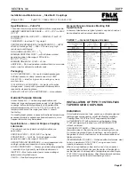
Power Curve ....................................................................................................................
CDDA - 5034 - 02
Page 47-A-2
DDFP-03DN
INSTALLATION & OPERATION DATA (Continued)
CDDA MAR 97 JTW
2100
2350
2600
Exhaust System
2100
2350
2800
3000
2350
2100
2600
2800
3000
2600
3000
2800
10 (3)
10 (3)
3.0 (76)
3.0 (76)
3.0 (76)
3.5 (89)
3.5 (89)
1470
1760
3.0 (76)
50.0 (189) 50.0 (189)
171 (4.8)
15 (2.3)
204 (5.8)
15 (2.3)
1760
1470
1470
1760
498 (14)
850 (454)
404 (11)
810 (432)
20 (5.0)
20 (5.0)
83 (572)
88 (607)
1103 (336) 1320 (402)
Содержание DDFP Series
Страница 13: ...DDFP SECTION 2 Front View V 71 Page 9 A Front View I 71 Right Side View I 71 Right Side View 6V 71 ...
Страница 14: ...Page 9 B SECTION 2 DDFP Front View 12V 92 Left Side View 12V 92 Front View V 92 Right Side View V 92 ...
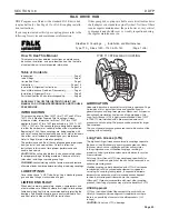
Страница 22: ...SECTION 3 2 DDFP AIR FILTER SERVICE INSTRUCTIONS Figure 1 Air Filter Service Instructions Page 17 ...
Страница 42: ...SECTION 3 5 DDFP Page 37 Fig 13 DC Wiring Diagram Engines With Mechanical Guages ...
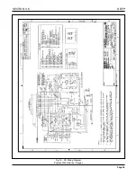
Страница 43: ...DDFP Fig 14 DC Wiring Diagram Engines With Electrical Guages Page 38 SECTION 3 5 ...
Страница 44: ...SECTION 3 5 DDFP Page 39 Fig 15 AC Wiring Diagram ...


