


DDFP
SECTION 3.4
Page 28
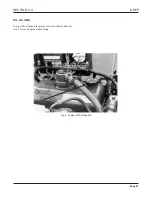
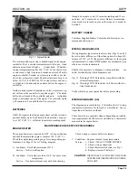
COOLANT PUMP
The engine water pump is a centrifugal impeller type pump.
It is gear dri ven on the I-71, V-71 and V-92 Series engines
and belt driven on the I-53 Series engines. The rebuildable
pump utilizes a shaft and sealed bearing assembly. The V-71
and V-92 incorporate an oil seal and tw o splash lubricat-
ed ball type bearings. Each pump also included a w
ater
pump seal weep hole. Should a coolant leak occur at this
location, the pump seal must be replaced. Contact your local
DDC Distrib utor/Dealer for assistance. Should a replace-
ment pump be required for repair , use only the e xact same
type of pump.
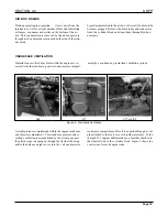
THERMOSTAT
Each pump engine is equipped with a temperature control-
ling thermostat(s). Normal operating ranges will vary due to
engine horsepower and operating speed. The thermostat(s)
are located at the front of the c
ylinder heads. Refer to
Section 5 for specif ic operating temperatures for each
engine.
ENGINE COOLANT HEATER
Fire pump engines must be able to assume full load imme-
diately when used for emergency service. NFPA-20 specifi-
cations require an engine coolant heater Figure 6, Page 29,
to maintain a minimum temperature of 120° F
. (49° C).
Maintaining this temperature assists the engine to start eas-
ily and produce rated horsepo wer immediately . F or f ire
pump units operation in cold climates optional oil heaters
are a vailable to k eep the engines lubricating oil at a safe
temperature for emer gency start purposes. If pump room
temperatures drop belo w 50° F (10° C),
oil heaters are
required.
On the initial installation of each f ire pump engine, it is the
responsibility of the installing contractor to wire the heater
to the pump room AC circuit. See Section 3 Electrical AC
Wiring Diagram, Page 39, for correct wiring to the heater
disconnect switch.
CAUTION:
Do not acti vate the AC circuit unless the
engine cooling system has been filled.
A pre-mix solution must be used. Chemical
reactions will occur if pure Ethylene Glycol
anti-freeze is allo wed to f ill the heater ca vity
with AC circuit is activated.
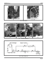
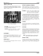
HEAT EXCHANGER COOLING
The heat e xchanger cooling system is illustrated in Fig.
1,
Page 25.
Raw water from the f ire pump passes through the heat e x-
changer core where it lowers the engine coolant temperature
10-15° F (-12° – -9° C). Typical raw water connection points
on the heat exchanger are shown in Fig.
7,
Page 29.
HOSES
Specific areas on each DDFP engine use hoses to transfer
coolant to and from heat exchangers and immersion heaters.
Regular inspections are necessary to v erify that no leaks
exist. Should replacements be required contact your local
DDC Distributor/Dealer for assistance.
NOTE:
Silicon Hose material for the immersion heaters
must meet SAE J20 Requirements with a maxi-
mum heat operating range of 350° F (177° C). Do
not replace these hoses with any other type materi-
al.
NOTE:
Hose clamps required for silicon type hose, must
have a shielded inner band or be of a constant
torque type (spring loaded). If the second type is
used, do not collapse spring by over tightening.
Содержание DDFP Series
Страница 13: ...DDFP SECTION 2 Front View V 71 Page 9 A Front View I 71 Right Side View I 71 Right Side View 6V 71 ...
Страница 14: ...Page 9 B SECTION 2 DDFP Front View 12V 92 Left Side View 12V 92 Front View V 92 Right Side View V 92 ...
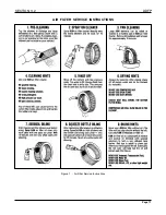
Страница 22: ...SECTION 3 2 DDFP AIR FILTER SERVICE INSTRUCTIONS Figure 1 Air Filter Service Instructions Page 17 ...
Страница 42: ...SECTION 3 5 DDFP Page 37 Fig 13 DC Wiring Diagram Engines With Mechanical Guages ...
Страница 43: ...DDFP Fig 14 DC Wiring Diagram Engines With Electrical Guages Page 38 SECTION 3 5 ...
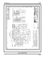
Страница 44: ...SECTION 3 5 DDFP Page 39 Fig 15 AC Wiring Diagram ...


