


Page 47-G-1
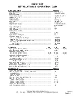
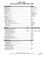
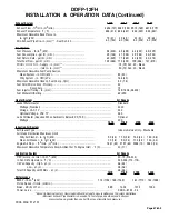
DDFP-06FA
INSTALLATION & OPERATION DATA
(Continued)
*Positive and Negative Cables Combined Length
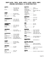
Basic Engine Description
All Speeds
Engine Manufacturer........................................................................................................
Detroit Diesel Corp.
Ignition Type ....................................................................................................................
Compression (Diesel)
Number of Cylinders ........................................................................................................
6
Bore and Stroke - in. (mm)..............................................................................................
4.84 x 5.00 (123 x 127)
Displacement - in.3 (L) ....................................................................................................
552 (9.1)
Compression Ratio ..........................................................................................................
17:1
Combustion System ........................................................................................................
Direct Injection
Engine Type......................................................................................................................
63.5˚ VEE - 2 Cycle
Aspiration ........................................................................................................................
Turbocharged
Firing Order (CW Rotation) ..............................................................................................
1R-1L-3R-3L-2R-2L
Charge Air Cooling Type ..................................................................................................
Jacket Water
Blower Type ....................................................................................................................
Roots By-Pass
Blower Drive Ratio ..........................................................................................................
1.95:1
Rotation (Viewed from Front)
Clockwise ....................................................................................................................
Standard
Counter-Clockwise ......................................................................................................
Optional
Engine Crankcase Vent System........................................................................................
Open
Dimensions and Weight
Length - in. (mm) (From Drive Flange)........................................................................
45.35 (1152)
Width - in. (mm) ..........................................................................................................
40.34 (1025)
Height - in. (mm) (Above Crankshaft Center Line) ....................................................
43.75 (1111)
Weight, Dry - lb. (kg) ..................................................................................................
2217 (1005)
Wet - lb. (kg) ........................................................................................................
2325 (1055)
Installation Drawing ........................................................................................................
D-433
Cooling System
1470
1760
2100
2350
Engine H2O Heat - Btu/sec. (kJ/sec.) ........................................................
206 (217)
233 (246)
260 (274) 284 (300)
Engine Radiated Heat - Btu/sec. (kJ/sec.)..................................................
42 (44)
Heat Exchanger Minimum Flow
60˚F Raw H2O - gal./min. (L/min.) ........................................................
13 (49)
21 (79)
26 (98)
28 (106)
95˚F Raw H2O - gal./min. (L/min.) ........................................................
22 (83)
32 (121)
39 (148) 42 (159)
Heat Exchanger Maximum Cooling H2O
Inlet Pressure - lb./in.2 (kPa) ......................................................................................
60 (44)
Flow - gal./min. (L/min.) ..............................................................................................
70 (265)
Thermostat, Start to Open - ˚F (˚C) ..................................................................................
177 (81)
Fully Open - ˚F (˚C) ................................................................................................
197 (92)
Engine Coolant Capacity - qt. (L) ....................................................................................
42 (40)
Coolant Pressure Cap - lb./in.2 (kPa) ..............................................................................
9 (62)
Maximum Engine H2O Temperature - ˚F (C) ....................................................................
200 (93)
Minimum Engine H2O Temperature - ˚F (˚C)....................................................................
160 (71)
Electric System - DC
All Speeds
System Voltage (Nominal) ..............................................................................................
24
Battery Capacity for Ambients Above 32˚F - CCA @ 0˚F ..................................................
900
Voltage (Nominal) ........................................................................................................
12
Qty. per Battery Bank ..................................................................................................
2
SAE size per J537 ........................................................................................................
8D-900
Battery Cable Circuit*, Max Resistance - ohm ................................................................
0.002
Battery Cable Minimum Size
0-225 in. Circuit* Length ........................................................................................
No. 00
225-300 in. Circuit* Length ........................................................................................
No. 000
301-380 in. Circuit* Length ........................................................................................
No. 0000
Charging Alternator Output - Amp. ..................................................................................
40
Starter Cranking Amps - @ 40˚ F ....................................................................................
595
Содержание DDFP Series
Страница 13: ...DDFP SECTION 2 Front View V 71 Page 9 A Front View I 71 Right Side View I 71 Right Side View 6V 71 ...
Страница 14: ...Page 9 B SECTION 2 DDFP Front View 12V 92 Left Side View 12V 92 Front View V 92 Right Side View V 92 ...
Страница 22: ...SECTION 3 2 DDFP AIR FILTER SERVICE INSTRUCTIONS Figure 1 Air Filter Service Instructions Page 17 ...
Страница 42: ...SECTION 3 5 DDFP Page 37 Fig 13 DC Wiring Diagram Engines With Mechanical Guages ...
Страница 43: ...DDFP Fig 14 DC Wiring Diagram Engines With Electrical Guages Page 38 SECTION 3 5 ...
Страница 44: ...SECTION 3 5 DDFP Page 39 Fig 15 AC Wiring Diagram ...


