


SECTION 2
DDFP
Page 9
Right Side View (I-53)
Front View (I-53)
engine coolant between 120 -140 de grees F (49-60° C).
When running, engine coolant temperature should re gister
between 180-200 de grees F (82-93° C). See Section 3 for
detailed information.
Crankcase
The oil le vel should be maintained between the
Full
mark
and
Low
mark. Check the oil le vel weekly prior to normal
exercise. The oil dipstick is located on the right side of the
engine. Do not check oil level when the engine is running. If
the engine crankcase was refilled, stop the engine after nor-
mal operating temperature has been reached, allow the oil to
drain back into the crankcase (approximately 10 minutes)
and check the oil le vel. Add oil, if necessary, to bring it to
the proper level on the dipstick.
NOTE:
DO NOT OVER-FILL CRANKCASE.
Use only the recommended lubricating oil specif ied under
Section
3
- Lubricating Oil.
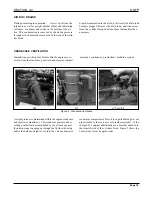
Running Inspection
While the engine is running at operating temperature, check
for coolant, fuel or lubricating oil leaks. Tighten the line
Drive Belts
Adjust the alternator drive belts as recommended under the
Preventive Maintenance Section
2.
Storage Battery
Check the batteries. The top should be clean and dry, the ter-
minals tight and protected, and the electrolyte must be at the
proper level. They should be tested weekly to determine the
condition of cells, and the amount of charge.
NOTE:
Once each week, check the batteries with a hy-
drometer; the corrected reading should be 1.265
or higher. Hydrometer readings should be cor-
rected for the temperature of the electrolyte.
Should a problem be detected, locate source and
correct.
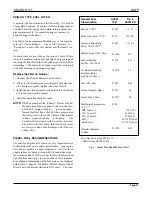
Oil Pressure
Normal engine operating oil pressure is 40-70 psi (276-433
kPa). If operating pressure falls below 30 psi (206 kPa), stop
engine and investigate cause.
Coolant Temperature
When unit is not running,
Jacket w ater heaters maintain
Standard Model Views
Содержание DDFP Series
Страница 13: ...DDFP SECTION 2 Front View V 71 Page 9 A Front View I 71 Right Side View I 71 Right Side View 6V 71 ...
Страница 14: ...Page 9 B SECTION 2 DDFP Front View 12V 92 Left Side View 12V 92 Front View V 92 Right Side View V 92 ...
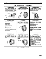
Страница 22: ...SECTION 3 2 DDFP AIR FILTER SERVICE INSTRUCTIONS Figure 1 Air Filter Service Instructions Page 17 ...
Страница 42: ...SECTION 3 5 DDFP Page 37 Fig 13 DC Wiring Diagram Engines With Mechanical Guages ...
Страница 43: ...DDFP Fig 14 DC Wiring Diagram Engines With Electrical Guages Page 38 SECTION 3 5 ...
Страница 44: ...SECTION 3 5 DDFP Page 39 Fig 15 AC Wiring Diagram ...


