


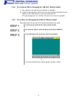


2
1.1.3
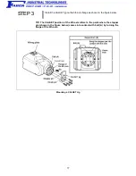
Connecting the Robot Unit and Robot Controller
Before delivery, the robot unit and the robot controller are configured as a set. If you
purchase two or more robot systems, take care not to mistake each set when
connecting robot units and controllers.
Caution: The robot unit and robot controller in a set are given the same
serial number.
1.1.4
Installation Environment of the Robot Unit
The installation requirements for the robot unit are shown below. Prepare a highly rigid
mount by referring to the figure on the next page.
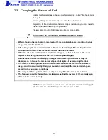
Caution Do not electric-weld the equipment including the robot. A large
current may flow through the motor encoder or robot controller
resulting in a failure. If electric welding is required, remove the
robot unit and the robot controller from the equipment beforehand.
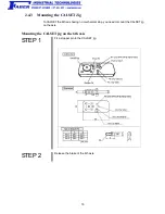
Installation Requirements for the Robot Unit
Item
Environments and Conditions
Flatness of the mount
0.1/500 mm (See the upper figure on the next page.)
Rigidity of the mount
Use steel materials. (See the figure on the next page.)
Installation type
Floor-mount or Overhead mount
Ambient temperature
During operation: 0 to 40
C
During storage and transportation: -10 to 60
C
Humidity
During operation: 90% or less (No dew condensation allowed.)
During storage and transportation: 75% or less (No dew condensation
allowed.)
Vibration
During operation: 4.9 m/s
2
(0.5G) or less
During storage and transportation: 29.4 m/s
2
(3G) or less
Altitude
During operation: 1,000 m or less
Safe installation
environment
Refer to the SAFETY PRECAUTIONS,
3.1 "Insuring the proper
installation environment"
Working space, etc.
• Sufficient service space must be available for inspection and disassembly.
• Keep wiring space (190 mm or more) behind the robot, and fasten the wiring
to the mounting face or beam so that the weight of the cables will not be
directly applied to the connectors.
Grounding conditions
Functional ground
See the figure on page 6.
Содержание VP-5243G
Страница 1: ...ROBOT Vertical articulated VP G SERIES INSTALLATION MAINTENANCE GUIDE ...
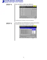
Страница 26: ...20 STEP 7 Press the SHIFT key and F12 Maint F12 STEP 8 Press F3 Brake F3 ...
Страница 47: ...41 STEP 3 The user counter of the controller ON time has been reset to zero as shown below ...
Страница 54: ......