background image


40


3.8.2


Resetting the User Counters of the Controller ON-Time and the 
Robot Running Time 


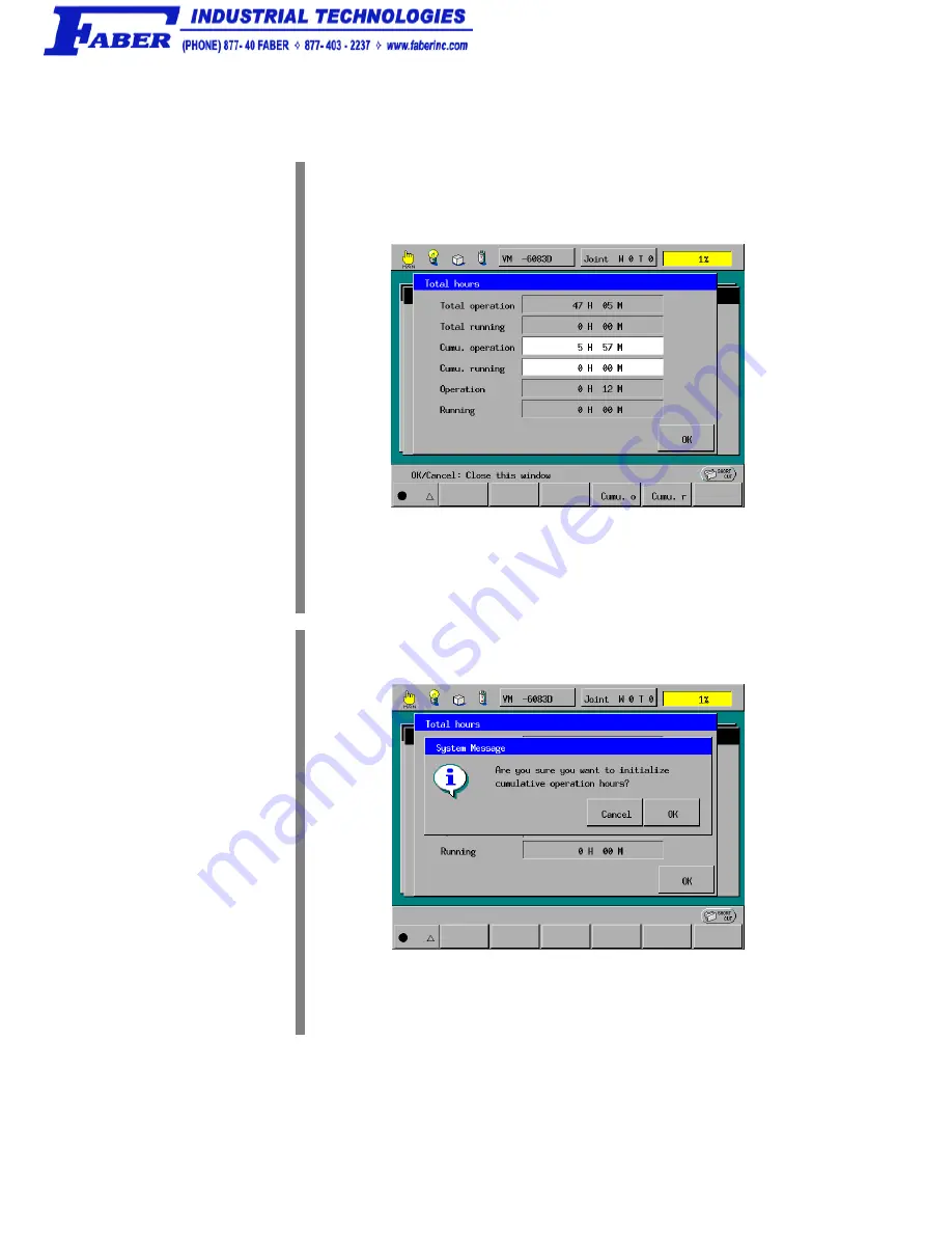
STEP 1


Display the Total hours window as shown below. 

Access: [F6 Set]—[F6 Maint.]— [F1 Total h] from the top screen 


F4 

To reset the user counter of the controller ON-time (Cumu.operation), for 
example, press [F4 Cumu. o]. 


STEP 2


The following system message appears. 


Press the OK button. 


Содержание VP-5243G

Страница 1: ...ROBOT Vertical articulated VP G SERIES INSTALLATION MAINTENANCE GUIDE ...

Страница 2: ...his publication may be reproduced in any form or by any means without permission in writing from the publisher Specifications are subject to change without prior notice All products and company names mentioned are trademarks or registered trademarks of their respective holders ...

Страница 3: ...this manual Series Model Mini sized vertical articulated VP G Models configured with RC7M controller VP 6242G 6 axis type VP 5243G 5 axis type NOTE 1 Model names listed above apply to the models of robot systems The model names of robot units are followed by M If the robot system model is VP 6242G for example the robot unit model is VP 6242E GM Important To ensure operator safety be sure to read t...

Страница 4: ...sical site planning installation procedures and engineering design notes for hands Chapter 2 Customizing Your Robot Describes how to customize your robot defining the software motion space and restricted space CALSETing and setting control set of motion optimization Chapter 3 Maintenance and Inspection Describes the regular maintenance and inspections necessary for maintaining the performance and ...

Страница 5: ...Out the Power Switch 7 Chapter 2 Customizing Your Robot 8 2 1 What Is Customization 8 2 2 Modifying Software Motion Limits to Define New Motion Space 9 2 2 1 What Is a Software Motion Limit 9 2 2 2 Factory Defaults of Software Motion Limits 9 2 2 3 Changing Software Motion Limits 10 2 2 4 Precautions When Changing the Software Motion Limits 11 2 2 5 Procedure for Changing the Software Motion Limit...

Страница 6: ...Next Battery Replacement Date 33 3 5 Supplies and Tools for maintenance 34 3 6 Replacing Fuses and Output ICs 34 3 7 Checking the Odometer and Trip Meter 35 3 7 1 Displaying the Odometer Trip Meter and Oil Change Intervals 35 3 7 2 Resetting the Trip Meter to Zero 37 3 8 Checking the Controller ON Time and the Robot Running Time and Resetting Their User Counters 38 3 8 1 Displaying the Controller ...

Страница 7: ... long and unexpected failure may result 1 1 1 Ambient Temperature and Humidity Keep the ambient temperature between 0 C and 40 C during operation Keep the ambient humidity at 90 or below to prevent dew condensation 1 1 2 Vibration Do not install the robot in an environment where it will be exposed to excessive vibration or impact Caution When the excessive vibration is added to the robot unit at p...

Страница 8: ...Environments and Conditions Flatness of the mount 0 1 500 mm See the upper figure on the next page Rigidity of the mount Use steel materials See the figure on the next page Installation type Floor mount or Overhead mount Ambient temperature During operation 0 to 40 C During storage and transportation 10 to 60 C Humidity During operation 90 or less No dew condensation allowed During storage and tra...

Страница 9: ...nt or slightly modify the robot speed Robot Mount Example for Floor mount Strut Mounting face 350 350 20 or more 100 100 t6 0 square steel pipe Caution 1 When the robot operates at high speed the top plate structure undergoes large reaction forces Design the vibration proof mount so that the top plate will not vibrate due to reaction forces Also design the top plate structure so that it separates ...

Страница 10: ... significant impacts when the arm fixing plate is not in place the arm angles may shift slightly and cause Error 6773 to be displayed on the controller Encoder resetting and CALSET must be performed if this occurs Axis angles when affixing the arm fixing plate degrees Axis VP 6242G VP 5243G J1 90 0000 90 0000 J2 40 0420 39 9915 J3 158 9266 128 9209 J4 0 0000 J5 61 1154 91 0706 J6 0 0000 0 0000 Not...

Страница 11: ... into the 4H7 hole so that it orients as shown below 3 Drive the internally threaded positioning pin into the 6H7 hole NOTE Be sure to drive the knock pins It can minimize positional deviations that may be caused by the removal installation of the robot unit for maintenance or the vibration during operation 4 Set the robot unit into place on the robot mount 5 Secure the robot unit to the mount wit...

Страница 12: ...ower or power equipment such as a welder Grounding the Robot Unit VP G series 1 3 Installing the Robot Controller For the installing procedures of the robot controller refer to the RC7M CONTROLLER MANUAL Section 6 2 Installing the Robot Controller 1 4 Cautions for Designing the Robot Hand Refer to the GENERAL INFORMATION ABOUT ROBOT for VP G SERIES Chapter 3 Section 3 5 Precautions When Designing ...

Страница 13: ...ng a commercially available padlock according to the following procedure Step 1 Check that the power switch of the robot controller is turned OFF Step 2 Remove the lockout bar provided on the robot controller Step 3 Put the lockout bar on the upper side of the power switch Step 4 Padlock the lockout bar ...

Страница 14: ...et of motion optimization Robot installation conditions You are recommended to define new motion space and restricted space in order to prevent interference with other devices or entanglement of the end effector wiring and piping WARNING Always set the software motion limits and mechanical ends so that the motion space will be within the restricted space Otherwise the robot will bump the mechanica...

Страница 15: ...ayed error code starting from 6070 the first digit represents the axis number and the robot will come to a stop The power to the motor is also turned OFF in such a case during automatic operation All axes are assigned a software motion limit in both the positive and negative direction of the operation range The software motion limit in the positive direction is called the positive direction softwa...

Страница 16: ... air piping or wiring of the end effector becomes taut as the robot runs then change the software motion limits to make the motion space smaller as shown in the lower figure on this page NOTE When changing software motion limits always make the new motion space smaller than the motion space defined by initial settings Example 1 Changing Software Motion Limits Example 2 Changing Software Motion Lim...

Страница 17: ...asurement If the operating space is too small the robot may seem to become inoperable 2 2 5 Procedure for Changing the Software Motion Limits Described below is the procedure for changing the software motion limits STEP 1 Turn the power switch of the robot controller to ON STEP 2 Set the mode selector switch of the teach pendant to MANUAL STEP 3 Press F2 Arm on the top screen of the teach pendant ...

Страница 18: ...ess the SHIFT key and then press F12 Maint F12 The Maintenance Functions Arm window will appear STEP 5 Press F1 M Space on the Maintenance Functions Arm window The Motion Space window will appear as shown below F5 ...

Страница 19: ...l be set on the line of the item selected in the Motion Space window If two or more items must be changed repeat Steps 5 and 6 STEP 7 Press OK in the Motion Space Software motion limit window STEP 8 Turn OFF the power to the robot controller Caution The new software motion limit s specified for the motion space will take effect after the robot controller restarts and CAL is completed ...

Страница 20: ...ation 3 When the robot has collided with a mechanical stopper contact us for inspection and repairs before using the robot because the robot may be damaged Also because the mechanical stopper designed and made by the customer may be damaged do not reuse the mechanical stopper but replace it before using the robot 4 The reference drawings described on this manual cannot be covered on the customer s...

Страница 21: ...xis having no mechanical stop you need to mount the CALSET jig on the axis 2 When CALSETing move the axis to be CALSET in the vicinity of the mechanical stop release the brake and bring the axis into contact with the mechanical stop In the VP G series each of all axes has a brake 3 When performing CALSET be careful with the robot motion The execution of the CALSET command releases motor brakes so ...

Страница 22: ...LSET Jig To CALSET the 6th axis having no mechanical stop you need to mount the CALSET jig on the axis Mounting the CALSET jig on the 6th axis STEP 1 Fit a stopper pin in the CALSET jig STEP 2 Release the brake of the 6th axis ...

Страница 23: ...th axis flange as shown in the figure below TIP The CALSET position of the 6th axis refers to the point where the stopper pin shown in the figure below comes into contact with bolt A by turning the flange of the 6th axis Mounting a CALSET Jig ...

Страница 24: ... 5th axis Turning end in the positive direction Position 6th axis Turning end in the positive direction which is set by a CALSET jig CALSET Positions VP 6242G VP 5243G Axis CALSET position 1st axis Turning end in the positive direction counterclockwise end when viewed from top 2nd axis Turning end in the negative direction 3rd axis Turning end in the positive direction 5th axis Turning end in the ...

Страница 25: ...given time because of interference between the robot unit and its surrounding facilities STEP 1 Turn the power switch of the robot controller to ON STEP 2 Set the mode selector switch of the teach pendant to MANUAL STEP 3 Press MOTOR to turn ON the power to the motor STEP 4 Move the axis to be CALSET in the vicinity of the mechanical stop via the manual operation from the teach pendant STEP 5 Pres...

Страница 26: ...20 STEP 7 Press the SHIFT key and F12 Maint F12 STEP 8 Press F3 Brake F3 ...

Страница 27: ...en display STEP 10 Confirm that there is no danger even if the arms fall as a result of released brakes CAUTION In the VP G series the brake of the specified axis is released STEP 11 Press OK The system message appears asking you whether you want to change the brake settings ...

Страница 28: ...ystem message appears informing that the brake is released and warning against drop of arms STEP 13 Press the axis to be CALSET against the mechanical stop by hand STEP 14 Press F6 CALSET The Set CALSET window appears F6 CALSET ...

Страница 29: ...k display for the other axes that are not required to be CALSET STEP 16 Press OK The system message appears asking whether you want to carry out CALSET and showing a caution that the robot reference position will change STEP 17 Press OK The system message appears informing that CALSET is completed ...

Страница 30: ... axis a little in the opposite direction of the mechanical end and turn ON the power again STEP 21 Move the CALSETed axis in the opposite direction from the mechanical end by the manual operation of the teach pendant STEP 22 Perform CAL The single axis CALSET of the specified axis is completed 2 4 5 2 CALSETing All Axes The CALSET of all axes is called all axis CALSET The procedure is the same as ...

Страница 31: ... and Control Set of Motion Optimization The payload center of gravity is represented by the TOOL0 coordinate system see the figure below in the unit of mm The origin of the TOOL0 coordinate system is the center of the 6th axis flange Its Y component is in the direction from the flange center to the 5H7 pin hole orientation vector direction The Z component is in the vertical direction to the flange...

Страница 32: ... it is set for floor mount If you overhead mount your robot you need to change the installation settings For the setting procedure refer to the SETTING UP MANUAL Section 2 9 Setting the Robot Installation Condition and the PROGRAMMER S MANUAL Section 4 7 3 Setting Robot Installation Conditions Z axis positive direction approach vector Y axis positive direction orientation vector X axis positive di...

Страница 33: ...ntenance Inspection Intervals and Purposes No Intervals Purposes 1 Daily Perform inspection jobs specified in Section 3 2 every day before starting operations To use your robot safely 2 Quarterly Perform inspection jobs specified in Section 3 3 every three months To maintain the precision of the robot and to prevent failures caused by overheat of the robot controller 3 Biennial Replace backup batt...

Страница 34: ...ir or replace 4 Pilot lamps on the robot controller ON Visually Should light Repair or replace 5 Cooling fan in the robot controller ON Visually Note 2 Should work properly Repair or replace 6 EMERGENCY STOP button on the teach pendant or the mini pendant ON Press the EMERGENCY STOP button The robot should come to an emergency stop Repair or replace 7 Safety door ON Operate the safety door switch ...

Страница 35: ... tightening torque with a torque wrench No looseness Specified torque 35 7 Nm Tighten the bolts to the specified torque 2 Cooling fan filters in the robot controller OFF Visually No dust or dirt Clean the cooling fan filters Refer to Section 3 3 2 3 3 2 Cleaning the Air Intake Filter in the Robot Controller For the cleaning procedures of the air intake filter refer to the RC7M CONTROLLER MANUAL Se...

Страница 36: ...tion data of the servomotor encoder In the robot unit Section 3 4 2 2 Memory backup battery Back up programs parameters and CAL data In the robot controller Section 3 4 3 The position data of the encoder built in the servomotor is stored in the internal memory of the encoder Programs parameters CAL data etc are stored in the internal memory of the robot controller The backup battery for each memor...

Страница 37: ... power ON Note When replacing the encoder backup battery do not turn the controller power OFF If you do so the encoder positional data may be lost STEP 3 Turn the motor power OFF when replacing the battery Note 1 Push the EMERGENCY STOP button on the teach pendant or mini pendant and the button is locked in the stop status 2 When rotating the EMERGENCY STOP button clockwise the button will be rele...

Страница 38: ...old batteries at the same time before connecting a new one If you do so the encoder positional data may be lost Note Be sure to replace all of three batteries with new ones at one time Otherwise the battery service life will become short STEP 6 Reinstall the cover to the robot unit Tightening torque Cross pan head screw 0 59 Nm ...

Страница 39: ...ct STEP 1 On the top screen of the teach pendant press F6 Set The Settings Main window appears STEP 2 Press F6 Maint in the Settings Main window The Maintenance menu appears STEP 3 Press F4 Battery in the Maintenance menu The Next Battery Replacement Date window appears In the top of the window the current setting is displayed The date entry areas show the default replacement date that is two year...

Страница 40: ... For RC7M controller 3 Fuse 1 3A 410054 0230 For LM13 for controller I O 4 Fuse 3 2A 410054 0270 For LM32 for controller I O 5 IC for output NPN 410077 0010 IC M54522P for controller output 6 IC for output PNP 410077 0020 IC M54564P for controller output 7 Encoder backup battery 410611 0070 3 battery set 8 CALSET jig 410192 0010 For 6th axis CALSET 3 6 Replacing Fuses and Output ICs For the replac...

Страница 41: ... the robot leaves the factory You cannot reset the odometer Trip meter Shows the distance of each axis traversed after you reset the trip meter to zero You can reset the trip meter by pressing F6 Reset in the Odometer window and following the guidance shown on the screen 3 7 1 Displaying the Odometer Trip Meter and Oil Change Intervals STEP 1 Turn the controller power ON STEP 2 On the teach pendan...

Страница 42: ...hown below F5 Press F5 Odometer STEP 5 The Odometer window appears as shown below F6 In the above Odometer window the J1 through J6 are expressed in rpm If the Trip meter count exceeds the Interval value the oil change prompt message will appear ...

Страница 43: ...eter to Zero STEP 1 Display the Odometer window as shown below Access F6 Set F6 Maint F5 Odometer from the top screen F6 Press F6 Reset STEP 2 The following message appears Press the OK button The trip meter has been reset to zero ...

Страница 44: ... time counted after the robot leaves the factory Cumu operation Shows the total of the robot controller ON time counted after you reset the user counter to zero Cumu running Shows the total of the robot running time counted after you reset the user counter to zero Operation Shows the ON time of the robot controller counted after it is turned ON this time Running Shows the running time of the robot...

Страница 45: ... after the robot leaves the factory Cumu operation Shows the total of the robot controller ON time counted after you reset the user counter to zero Cumu running Shows the total of the robot running time counted after you reset the user counter to zero Operation Shows the ON time of the robot controller counted after it is turned ON this time Running Shows the running time of the robot counted afte...

Страница 46: ...unning Time STEP 1 Display the Total hours window as shown below Access F6 Set F6 Maint F1 Total h from the top screen F4 To reset the user counter of the controller ON time Cumu operation for example press F4 Cumu o STEP 2 The following system message appears Press the OK button ...

Страница 47: ...41 STEP 3 The user counter of the controller ON time has been reset to zero as shown below ...

Страница 48: ...n encoder backup batteries or Error 677 occurs due to a great impact applied to the robot when the power is off is any of 1 to 6 denoting the object axis This section describes how to reset encoders For the encoder resetting procedure refer to the SETTING UP MANUAL Section 5 3 F2 Arm F12 Maint M11 ENC rest ...

Страница 49: ...ging RANG values after replacement of a motor DENSO preserves arm data configured at the time of shipment for 10 years If your arm data is lost contact your DENSO representative Note Arm data refers to CALSET and RANG values in project data which is unique to individual robots and determines the position of each joint 3 10 1 Back up project data Use WINCAPSIII to back up project data When a projec...

Страница 50: ...oose Get information from the controller for creating a new project STEP 3 Following the project wizard enter the IP address and the desired backup file name STEP 4 Select Receive data from the controller after creating the project STEP 5 Close the project ...

Страница 51: ...data has been backed up open the project data in WINCAPSIII and proceed to STEP 2 Start WINCAPSIII log on as a Programmer and create a project suitable for your robot model Choose Tool Arm parameters to display the Arm Parameter window Press Load and select the arm data wam to load STEP 2 Configuring communication options for transfer of arm data from WINCAPSIII to the robot controller Choose Tool...

Страница 52: ...obot controller Choose Connect Transfer data to display the Transfer data window Select Parameters Arm parameters and Configuration CALSET then press Send Upon completion of transfer of the CALSET related arm data restart the robot controller ...

Страница 53: ...al is to provide accurate information in the handling and operating of the robot Please feel free to send your comments regarding any errors or omissions you may have found or any suggestions you may have for generally improving the manual In no event will DENSO WAVE INCORPORATED be liable for any direct or indirect damages resulting from the application of the information in this manual 10N C ...

Страница 54: ......

Отзывы: