background image

Steps
1.

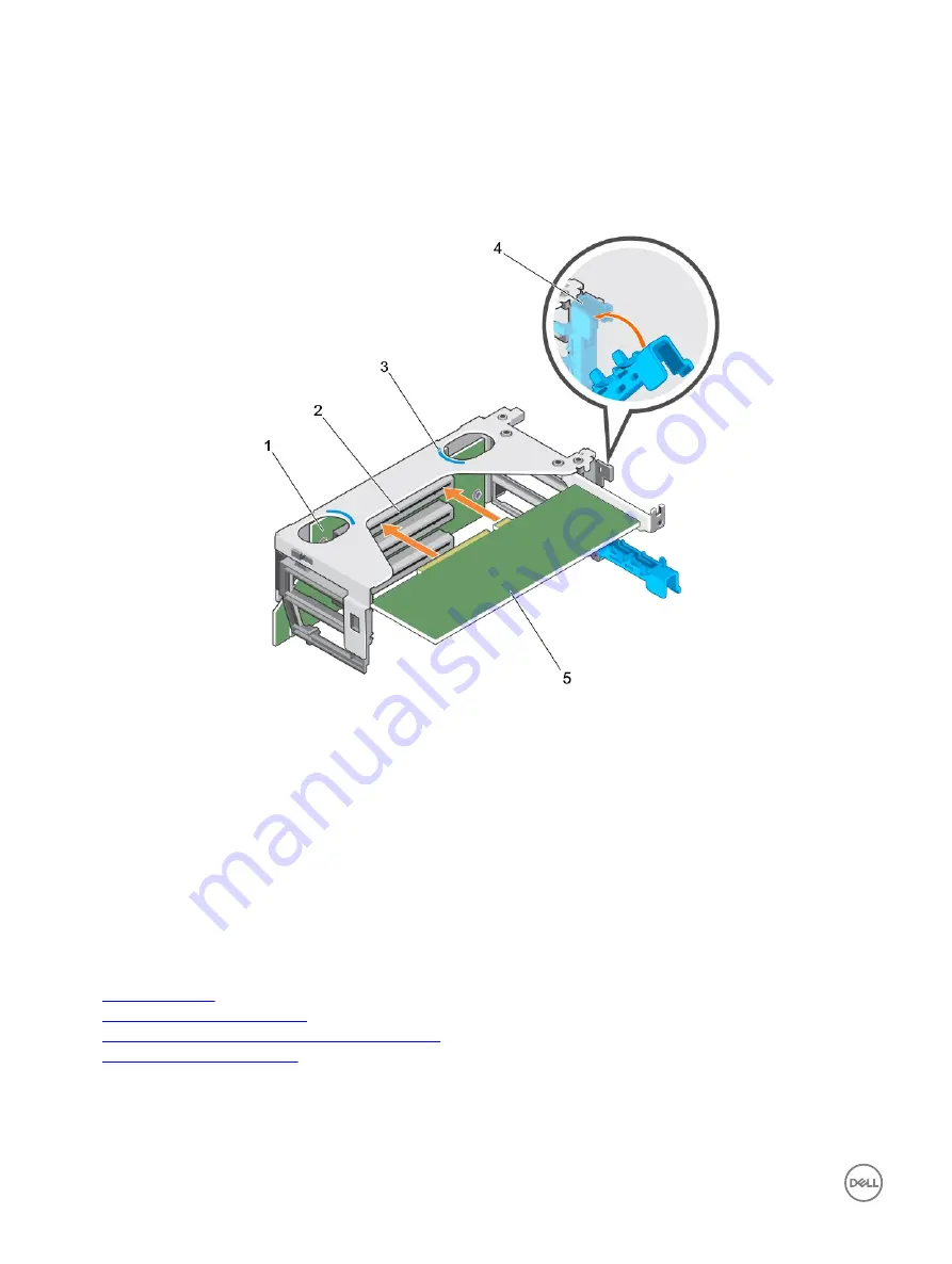
If applicable, unpack the expansion card and prepare it for installation. For instructions, see the documentation accompanying 
the card.

2.

Open the expansion card latch and remove the filler bracket.

3.

Holding the card by its edges, insert the card edge connector firmly into the expansion card connector until the card is fully 
seated.

Figure 56. Installing an expansion card into the expansion card riser 2

1.

expansion card riser 2

2.

expansion card connector

3.

touch point (2)

4.

expansion card latch

5.

expansion card

4.

Close the expansion card latch into the slot.

Next steps

1.

Install the expansion card riser 2.

2.

Follow the procedure listed in the After working inside your system section.

3.

Install any device drivers needed for the card as described in the documentation for the card.

Related links

Safety instructions
Before working inside your system
Removing an expansion card from expansion card riser 2
After working inside your system

114

Содержание PowerEdge R830

Страница 1: ...Dell PowerEdge R830 Owner s Manual Regulatory Model E21S Series Regulatory Type E21S002 ...

Страница 2: ... the problem WARNING A WARNING indicates a potential for property damage personal injury or death 2016 Dell Inc All rights reserved This product is protected by U S and international copyright and intellectual property laws Dell and the Dell logo are trademarks of Dell Inc in the United States and or other jurisdictions All other marks and names mentioned herein may be trademarks of their respecti...

Страница 3: ...ications 23 PSU specifications 23 System battery specifications 23 Expansion bus specifications 23 Memory specifications 23 Drive specifications 23 Hard drives 23 Optical drive 24 Ports and connectors specifications 24 USB ports 24 NIC ports 24 Serial connector 24 VGA ports 24 Internal Dual SD Module 24 Video specifications 24 Environmental specifications 25 Particulate and gaseous contamination s...

Страница 4: ... 55 Recommended tools 56 Front bezel optional 56 Removing the optional front bezel 56 Installing the optional front bezel 57 System cover 58 Removing the system cover 58 Installing the system cover 59 Inside the system 60 Processor expansion module optional 62 Removing the processor expansion module 62 Installing the processor expansion module 65 Cooling shroud 67 Removing the cooling shroud 67 In...

Страница 5: ...Installing an expansion card into expansion card riser 2 113 Removing an expansion card from the expansion card riser 3 115 Installing an expansion card into expansion card riser 3 116 Internal dual SD module optional 118 Removing an internal SD card 119 Installing an internal SD card 120 Removing the optional internal dual SD module 121 Installing the optional internal dual SD module 122 Network ...

Страница 6: ...m Diagnostics from Boot Manager 155 Running the Embedded System Diagnostics from the Dell Lifecycle Controller 155 System diagnostic controls 155 8 Jumpers and connectors 157 System board jumper settings 157 System Board Connectors 158 Disabling a forgotten password 160 9 Troubleshooting your system 162 Safety first for you and your system 162 Troubleshooting system startup failure 162 Troubleshoo...

Страница 7: ...Troubleshooting a tape backup unit 171 Troubleshooting a hard drive 171 Troubleshooting a storage controller 172 Troubleshooting expansion cards 173 Troubleshooting processors 174 System messages 174 Warning messages 174 Diagnostic messages 174 Alert messages 174 10 Getting help 175 Contacting Dell 175 Documentation feedback 175 Accessing system information by using QRL 175 Quick Resource Locator ...

Страница 8: ... E5 4600 v4 processors 48 DIMMs 16 hard drives or solid state drives NOTE Your system supports only hot swappable hard drives Two power supply units Supported configurations for the PowerEdge R830 system The Dell PowerEdge R830 system supports the following configurations Figure 1 Supported configurations for a two processor PowerEdge R830 system 8 ...

Страница 9: ...Figure 2 Supported configurations for a four processor PowerEdge R830 system 9 ...

Страница 10: ...irect 12 Optical drive Table 1 Front panel features 2 5 inch hard drive chassis Item Indicator button or connector Icon Description 1 Power button Press the power button to turn the system on or off The indicator on the button indicates if the system is on or off NOTE To gracefully shut down an ACPI compliant operating system press the power button 2 NMI button Press the NMI button to troubleshoot...

Страница 11: ... iDRAC Direct port to connect USB devices to the system or provide access to the iDRAC Direct features The USB management port is USB 2 0 compliant For more information see the Integrated Dell Remote Access Controller User s Guide at Dell com idracmanuals 12 Optical drive optional For information about the supported optical drive see the Technical specifications section Related links Technical spe...

Страница 12: ...ft or Right 2 To navigate to the Home screen from another menu complete the following steps a Press and hold the navigation button till the up arrow is displayed b Navigate to the using the up arrow c Select the Home icon d On the Home screen press the Select button to enter the main menu Setup menu NOTE When you select an option in the Setup menu you must confirm the option before proceeding to t...

Страница 13: ... Host Model or User String for the system Number Displays the Asset tag or the Service tag for the system Power Displays the power output of the system in BTU hr or Watts The display format can be configured in the Set home submenu of the Setup menu Temperature Displays the temperature of the system in Celsius or Fahrenheit The display format can be configured in the Set home submenu of the Setup ...

Страница 14: ...n for more than five seconds to enter the BIOS progress mode 7 System identification port Use the system identification port to connect the system status indicator assembly through the optional cable management arm 8 iDRAC8 Enterprise port Use the iDRAC8 Enterprise port to remotely access iDRAC For more information see the Integrated Dell Remote Access Controller User s Guide at Dell com idracmanu...

Страница 15: ... the appropriate Online Diagnostics test Restart the system and run embedded diagnostics ePSA If the hard drives are configured in a RAID array restart the system and enter the host adapter configuration utility program Electrical indicator The indicator flashes amber if the system experiences an electrical error for example voltage out of range or a failed power supply unit PSU or voltage regulat...

Страница 16: ... indicator on the right side does not turn on Table 5 Hard drive indicator codes Drive status indicator pattern RAID only Condition Flashes green twice per second Identifying drive or preparing for removal Off Drive ready for insertion or removal NOTE The drive status indicator remains off until all hard drives are initialized after the system is turned on Drives are not ready for insertion or rem...

Страница 17: ...n A Link and activity indicators are off The NIC is not connected to the network B Link indicator is green The NIC is connected to a valid network at its maximum port speed 1 Gbps or 10 Gbps C Link indicator is amber The NIC is connected to a valid network at less than its maximum port speed D Activity indicator is flashing green Network data is being sent or received Power supply unit indicator c...

Страница 18: ...mance EPP label on the back NOTE Mixing PSUs from previous generations of Dell PowerEdge servers can result in a PSU mismatch condition or failure to turn the system on D Flashing amber Indicates a problem with the PSU CAUTION When correcting a PSU mismatch replace only the PSU with the flashing indicator Swapping the PSU to make a matched pair can result in an error condition and unexpected syste...

Страница 19: ...ed by a unique Express Service Code and Service Tag number The Express Service Code and Service Tag are found on the front of the system by pulling out the information tag Alternatively the information may be on a sticker on the chassis of the system This information is used by Dell to route support calls to the appropriate personnel 19 ...

Страница 20: ... the operating system documentation Dell com operatingsystemmanuals For information about understanding Remote Access Controller Admin RACADM subcommands and supported RACADM interfaces see the RACADM Command Line Reference Guide for iDRAC Dell com idracmanuals For information about updating drivers and firmware see the Methods to download firmware and drivers section in this document Dell com sup...

Страница 21: ...nd enabling alerts for events on servers and components using the Dell Chassis Management Controller CMC see the CMC User s Guide Dell com esmmanuals Working with Dell PowerEdge RAID controllers For information about understanding the features of the Dell PowerEdge RAID controllers PERC and deploying the PERC cards see the Storage controller documentation Dell com storagecontrollermanuals Understa...

Страница 22: ...owerEdge R830 system X Xa Y Z with bezel Zb without bezel Za with bezel Za without bezel 482 4 mm 18 99 inches 434 0 mm 17 08 inches 86 8 mm 3 42 inches 777 6 mm 30 61 inches 740 6 mm 29 16 inches 35 7 mm 1 41 inches 20 4 mm 0 80 inches Chassis weight Table 10 Chassis weight System Maximum weight with all hard drives SSDs Minimum weight without any hard drives PowerEdge R830 31 7 kg 69 89 lb 10 5 ...

Страница 23: ...ystem battery specifications The PowerEdge R830 system supports CR 2032 3 0 V lithium coin cell system battery Expansion bus specifications The PowerEdge R830 system supports PCI express PCIe generation 3 expansion cards which need to be installed on the system board using expansion card risers This system supports three types of expansion card risers Memory specifications The PowerEdge R830 syste...

Страница 24: ...rt NIC ports The PowerEdge R830 system supports four Network Interface Controller NIC ports on the back panel which are available in the following two configurations four 1 Gbps or two 10 Gbps NOTE You can install up to six PCIe add on NIC cards Serial connector The serial connector connects a serial device to the system The PowerEdge R830 system supports one serial connector on the back panel whi...

Страница 25: ...rating Temperature section Maximum temperature gradient operating and storage 20 C h 68 F h Table 17 Relative humidity specifications Relative humidity Specifications Storage 5 to 95 RH with 33 C 91 F maximum dew point Atmosphere must be non condensing at all times Operating 5 to 85 relative humidity with 29 C 84 2 F maximum dew point Table 18 Maximum vibration specifications Maximum vibration Spe...

Страница 26: ...sult in equipment damage or failure you may need to rectify the environmental conditions Re mediation of environmental conditions is the responsibility of the customer Table 22 Particulate contamination specifications Particulate contamination Specifications Air filtration Data center air filtration as defined by ISO Class 8 per ISO 14644 1 with a 95 upper confidence limit NOTE This condition appl...

Страница 27: ...as 5 C and as high as 40 C For temperatures between 35 C and 40 C de rate maximum allowable temperature by 1 C per 175 m above 950 m 1 F per 319 ft 1 of annual operating hours 5 C to 45 C at 5 to 90 RH with 29 C dew point NOTE Outside the standard operating temperature 10 C to 35 C the system can operate down to 5 C or up to 45 C for a maximum of 1 of its annual operating hours For temperatures be...

Страница 28: ...ns to set up iDRAC IP address You must configure the initial network settings based on your network infrastructure to enable the communication to and from iDRAC You can set up the IP address by using one of the following interfaces Interfaces Document Section iDRAC Settings utility See Dell Integrated Dell Remote Access Controller User s Guide at Dell com idracmanuals Dell Deployment Toolkit See D...

Страница 29: ...l com ossupport Installation and How to videos for supported operating systems on Dell PowerEdge systems Supported Operating Systems for Dell PowerEdge Systems Methods to download firmware and drivers You can download the firmware and drivers by using any of the following methods Table 27 Firmware and drivers Methods Location From the Dell Support site Dell com support home Using Dell Remote Acces...

Страница 30: ...Product to allow the system to automatically detect your Service Tag or under General support navigate to your product 3 Click Drivers Downloads The drivers that are applicable to your selection are displayed 4 Download the drivers to a USB drive CD or DVD 30 ...

Страница 31: ...ce settings of your system NOTE Help text for the selected field is displayed in the graphical browser by default To view the help text in the text browser press F1 You can access system setup by using two methods Standard graphical browser The browser is enabled by default Text browser The browser is enabled by using Console Redirection Related links System Setup details Viewing System Setup View...

Страница 32: ... utility Device Settings System BIOS You can use the System BIOS screen to edit specific functions such as boot order system password setup password set the RAID mode and enable or disable USB ports Related links System BIOS Settings details Boot Settings Network Settings System Security System Information Memory Settings Processor Settings SATA Settings Integrated Devices Serial Communication Sys...

Страница 33: ... and options System Profile Settings Specifies options to change the processor power management settings memory frequency and so on System Security Specifies options to configure the system security settings such as system password setup password Trusted Platform Module TPM security It also manages the power and NMI buttons on the system Miscellaneous Settings Specifies options to change the syste...

Страница 34: ... only the first hard drive in the list is attempted to boot When this option is set to Enabled all hard drives are attempted to boot in the order selected in the Hard Disk Drive Sequence This option is not enabled for UEFI Boot Mode Boot Option Settings Configures the boot sequence and the boot devices BIOS Boot Settings Enables or disables BIOS boot options NOTE This option is enabled only if the...

Страница 35: ...d then click Yes to save the settings on exit Related links Boot Settings Boot Settings details Viewing Boot Settings Network Settings You can use the Network Settings screen to modify PXE device settings The network settings option is available only in the UEFI mode NOTE The BIOS does not control network settings in the BIOS mode For the BIOS boot mode the optional Boot ROM of the network control...

Страница 36: ...UEFI iSCSI Settings To view the UEFI iSCSI Settings screen perform the following steps 1 Turn on or restart your system 2 Press F2 immediately after you see the following message F2 System Setup NOTE If your operating system begins to load before you press F2 wait for the system to finish booting and then restart your system and try again 3 On the System Setup Main Menu screen click System BIOS 4 ...

Страница 37: ...S NI Improves the speed of applications by performing encryption and decryption by using the Advanced Encryption Standard Instruction Set AES NI This option is set to Enabled by default System Password Sets the system password This option is set to Enabled by default and is read only if the password jumper is not installed in the system Setup Password Sets the setup password This option is read on...

Страница 38: ...IOS uses the system manufacturer s key and certificates to authenticate pre boot images When Secure Boot policy is set to Custom the BIOS uses the user defined key and certificates Secure Boot policy is set to Standard by default Secure Boot Policy Summary Specifies the list of certificates and hashes that secure boot uses to authenticate images Related links System Security Viewing System Securit...

Страница 39: ... 3 On the System Security screen ensure that Password Status is set to Unlocked 4 In the System Password field alter or delete the existing system password and then press Enter or Tab 5 In the Setup Password field alter or delete the existing setup password and then press Enter or Tab If you change the system and setup password a message prompts you to reenter the new password If you delete the sy...

Страница 40: ... click System Information Related links System Information System Information details The System Information screen details are explained as follows Option Description System Model Name Specifies the system model name System BIOS Version Specifies the BIOS version installed on the system System Management Engine Version Specifies the current version of the Management Engine firmware System Service...

Страница 41: ...ltage Specifies the system memory voltage Video Memory Specifies the amount of video memory System Memory Testing Specifies whether the system memory tests are run during system boot Options are Enabled and Disabled This option is set to Disabled by default Memory Operating Mode Specifies the memory operating mode The options available are Optimizer Mode Advanced ECC Mode Mirror Mode Spare Mode Sp...

Страница 42: ...xplained as follows Option Description Logical Processor Enables or disables the logical processors and displays the number of logical processors If this option is set to Enabled the BIOS displays all the logical processors If this option is set to Disabled the BIOS displays only one logical processor per core This option is set to Enabled by default QPI Speed Enables you to control QuickPath Inte...

Страница 43: ...e This option is set to Nominal by default NOTE This option is only available on certain stock keeping units SKUs of the processors X2Apic Mode Enables or disables the X2Apic mode Dell Controlled Turbo Controls the turbo engagement Enable this option only when System Profile is set to Performance NOTE Depending on the number of installed CPUs there may be up to four processor listings Number of Co...

Страница 44: ...e only for ATA and AHCI modes Write Cache Enables or disables the command for Embedded SATA drives during POST Port A Sets the drive type of the selected device For Embedded SATA settings in ATA mode set this field to Auto to enable BIOS support Set it to OFF to turn off BIOS support For AHCI or RAID mode BIOS support is always enabled Option Description Model Specifies the drive model of the sele...

Страница 45: ...d device For Embedded SATA settings in ATA mode set this field to Auto to enable BIOS support Set it to OFF to turn off BIOS support For AHCI or RAID mode BIOS support is always enabled Option Description Model Specifies the drive model of the selected device Drive Type Specifies the type of drive attached to the SATA port Capacity Specifies the total capacity of the hard drive This field is undef...

Страница 46: ...BIOS support is always enabled Option Description Model Specifies the drive model of the selected device Drive Type Specifies the type of drive attached to the SATA port Capacity Specifies the total capacity of the hard drive This field is undefined for removable media devices such as optical drives Port J Sets the drive type of the selected device For Embedded SATA settings in ATA mode set this f...

Страница 47: ...ID Controller Enables or disables the integrated RAID controller This option is set to Enabled by default Integrated Network Card 1 Enables or disables the integrated network card Embedded NIC1 and NIC2 NOTE The Embedded NIC1 and NIC2 options are only available on systems that do not have Integrated Network Card 1 Enables or disables the Embedded NIC1 and NIC2 options If set to Disabled the NIC ma...

Страница 48: ... steps 1 Turn on or restart your system 2 Press F2 immediately after you see the following message F2 System Setup NOTE If your operating system begins to load before you press F2 wait for the system to finish booting and then restart your system and try again 3 On the System Setup Main Menu screen click System BIOS 4 On the System BIOS screen click Serial Communication Related links Serial Commun...

Страница 49: ...his option is set to Enabled by default Related links Serial Communication Viewing Serial Communication System Profile Settings You can use the System Profile Settings screen to enable specific system performance settings such as power management Related links System Profile Settings details System BIOS Viewing System Profile Settings Viewing System Profile Settings To view the System Profile Sett...

Страница 50: ...l scrub frequency This option is set to Standard by default Memory Refresh Rate Sets the memory refresh rate to either 1x or 2x This option is set to 1x by default Uncore Frequency Enables you to select the Processor Uncore Frequency option Dynamic mode enables the processor to optimize power resources across the cores and uncore during runtime The optimization of the uncore frequency to either sa...

Страница 51: ...set whether the system boots with the NumLock enabled or disabled This option is set to On by default NOTE This option does not apply to 84 key keyboards F1 F2 Prompt on Error Enables or disables the F1 F2 prompt on error This option is set to Enabled by default The F1 F2 prompt also includes keyboard errors Load Legacy Video Option ROM Enables you to determine whether the system BIOS loads the le...

Страница 52: ...S Entering the iDRAC Settings utility Changing the thermal settings Entering the iDRAC Settings utility 1 Turn on or restart the managed system 2 Press F2 during Power on Self test POST 3 On the System Setup Main Menu page click iDRAC Settings The iDRAC Settings screen is displayed Related links iDRAC Settings utility Changing the thermal settings The iDRAC settings utility enables you to select a...

Страница 53: ...ystem see the Dell Lifecycle Controller documentation at Dell com idracmanuals Related links Dell Lifecycle Controller Boot Manager The Boot Manager screen enables you to select boot options and diagnostic utilities Related links Boot Manager main menu System BIOS Viewing Boot Manager Viewing Boot Manager To enter Boot Manager 1 Turn on or restart your system 2 Press F11 when you see the following...

Страница 54: ...S boot menu enables you to select a boot device to boot from Related links Boot Manager System Utilities System Utilities contains the following utilities that can be launched Launch Diagnostics BIOS Update File Explorer Reboot System Related links Boot Manager PXE boot You can use the Preboot Execution Environment PXE option to boot and configure the networked systems remotely NOTE To access the ...

Страница 55: ...le working on components inside the system NOTE To ensure proper operation and cooling all bays in the system and system fans must be populated always with a component Before working inside your system Prerequisites Follow the safety guidelines listed in the Safety instructions section Steps 1 Turn off the system including any attached peripherals 2 Disconnect the system from the electrical outlet...

Страница 56: ...ront side of the server and prevents accidents while removing the hard drive or when pressing the reset or power button The front bezel can also be locked for additional security Removing the optional front bezel Prerequisites Follow the safety guidelines listed in the Safety instructions section Steps 1 Locate and remove the bezel key NOTE The bezel key is attached to the back of the bezel 2 Unlo...

Страница 57: ...el Installing the optional front bezel Prerequisites Follow the safety guidelines listed in the Safety instructions section Steps 1 Locate and remove the bezel key NOTE The bezel key is attached to the back of the bezel 2 Hook the right end of the bezel onto the chassis 3 Fit the free end of the bezel onto the system 4 Lock the bezel by using the key 57 ...

Страница 58: ...g the system cover Prerequisites 1 Follow the safety guidelines listed in the Safety instructions section 2 If installed remove the optional bezel Steps 1 Rotate the latch release lock counter clockwise to the unlocked position 2 Lift the latch toward the back of the system The system cover slides back and the tabs on the system cover disengage from the slots on the chassis NOTE The position of th...

Страница 59: ...ction 2 Ensure that all internal cables are connected and placed out of the way and no tools or extra parts are left inside the system Steps 1 Align the slots on the system cover with the tabs on the chassis 2 Push the system cover latch down The system cover slides forward and the slots on the system cover engage with the tabs on the chassis The system cover latch locks into place when the system...

Страница 60: ...Inside the system CAUTION Many repairs may only be done by a certified service technician You should only perform troubleshooting and simple repairs as authorized in your product documentation or as directed by the online or telephone service and support team Damage due to servicing that is not authorized by Dell is not covered by your warranty Read and follow the safety instructions that are ship...

Страница 61: ...Figure 14 Inside the system Two processor system 1 cooling fans 6 2 processors 2 3 DIMMs 12 4 power supply unit PSU 2 5 PSU connector 6 riser 3 7 riser 2 8 riser 1 9 DIMMs 12 61 ...

Страница 62: ...ocessor expansion module Prerequisites CAUTION Many repairs may only be done by a certified service technician You should only perform troubleshooting and simple repairs as authorized in your product documentation or as directed by the online or telephone service and support team Damage due to servicing that is not authorized by Dell is not covered by your warranty Read and follow the safety instr...

Страница 63: ...our system section Steps 1 Lift the release lever on the PEM until the PEM disengages from the chassis Figure 16 Disengaging the PEM 1 processor expansion module 2 release lever 2 Holding the release lever and a support pin lift the PEM away from the chassis 63 ...

Страница 64: ...l a cooling shroud NOTE You must install a filler bracket over the QPI connector to maintain the Federal Communications Commission FCC certification of the system The filler bracket keeps dust and dirt out of the system 4 To install the filler bracket align the notches on the filler bracket with the standoffs on the QPI connector and press the filler bracket into place 64 ...

Страница 65: ...epairs as authorized in your product documentation or as directed by the online or telephone service and support team Damage due to servicing that is not authorized by Dell is not covered by your warranty Read and follow the safety instructions that are shipped with your product 1 Before upgrading your system download the latest system BIOS version from Dell com support and follow the instructions...

Страница 66: ...e remove the PEM power connector cap 3 By holding the support pin and the release lever align the alignment guides on the PEM with the alignment guides on the chassis and lower the PEM into the chassis Figure 20 Installing the PEM 1 QPI connector 2 standoff 3 3 PEM power connector 2 4 alignment guide 2 66 ...

Страница 67: ...odynamically directs the airflow across the entire system The airflow passes through all the critical parts of the system where the vacuum pulls air across the entire surface area of the heat sink thus allowing increased cooling Removing the cooling shroud Prerequisites CAUTION Many repairs may only be done by a certified service technician You should only perform troubleshooting and simple repair...

Страница 68: ...ated links Safety instructions Before working inside your system Installing the cooling shroud After working inside your system Installing the cooling shroud Prerequisites CAUTION Many repairs may only be done by a certified service technician You should only perform troubleshooting and simple repairs as authorized in your product documentation or as directed by the online or telephone service and...

Страница 69: ... on the cooling shroud with the slots on the chassis 2 Lower the cooling shroud into the chassis until it is firmly seated Figure 23 Installing the cooling shroud 1 slot on the chassis 4 2 touch point 2 3 cooling shroud 4 guide slot on the cooling shroud 4 Next steps 1 Follow the procedure listed in the After working inside your system section Related links Safety instructions Before working insid...

Страница 70: ...and support team Damage due to servicing that is not authorized by Dell is not covered by your warranty Read and follow the safety instructions that are shipped with your product CAUTION The cooling fans are hot swappable To maintain proper cooling while the system is on replace only one fan at a time CAUTION Do not operate the system with the cover removed or the cooling fan removed for a duratio...

Страница 71: ...h your product 1 Follow the safety guidelines listed in the Safety instructions section 2 Follow the procedure listed in the Before working inside your system section NOTE The procedure for installing each fan is identical Steps 1 Align the connector at the base of the cooling fan with the connector on the system board 2 Slide the cooling fan into the securing slot until the tab locks into place F...

Страница 72: ...tified service technician You should only perform troubleshooting and simple repairs as authorized in your product documentation or as directed by the online or telephone service and support team Damage due to servicing that is not authorized by Dell is not covered by your warranty Read and follow the safety instructions that are shipped with your product Steps 1 Unlock the cooling fan assembly fr...

Страница 73: ...anty Read and follow the safety instructions that are shipped with your product 1 Follow the safety guidelines listed in Safety instructions section 2 Follow the procedure listed in the Before working inside your system section CAUTION Ensure that the cables are correctly installed and retained by the cable retention bracket before installing the cooling fan assembly Incorrectly installed cables m...

Страница 74: ...s DIMM speed in MegaTransfers per second Memory bus operating frequency can be 1866 MT s 2133 MT s or 2400 MT s depending on the following factors DIMM type RDIMM or LRDIMM Number of DIMMs populated per channel System profile selected for example Performance Optimized Custom or Dense Configuration Optimized Maximum supported DIMM frequency of the processors Your system contains 24 memory sockets s...

Страница 75: ...Figure 28 Memory socket locations 75 ...

Страница 76: ...and B11 Slots B4 B8 and B12 Processor 3 Slots C1 C5 and C9 Slots C2 C6 and C10 Slots C3 C7 and C11 Slots C4 C8 and C12 Processor 4 Slots D1 D5 and D9 Slots D2 D6 and D10 Slots D3 D7 and D11 Slots D4 D8 and D12 The following table shows the memory populations and operating frequencies for the supported configurations Table 29 Memory population DIMM Type DIMMs Populated Channel Voltage Operating Fre...

Страница 77: ...es with highest capacity first For example if you want to mix 4 GB and 8 GB memory modules populate 8 GB memory modules in the sockets with white release tabs and 4 GB memory modules in the sockets with black release tabs In a dual processor configuration the memory configuration for each processor should be identical For example if you populate socket A1 for processor 1 then populate socket B1 fo...

Страница 78: ... event of an uncorrectable error the system switches over to the mirrored copy This ensures SDDC and multi bit protection The installation guidelines for memory modules are as follows Memory modules must be identical in size speed and technology Memory modules installed in memory module sockets with white release levers must be identical and the same rule applies for sockets with black and green r...

Страница 79: ...1R x8 2133 MT s 1R x8 2400 MT s A1 A2 A3 A4 B1 B2 B3 B4 96 8 24 1R x8 1600 MT s 1R x8 1866 MT s A1 A2 A3 A4 A5 A6 A7 A8 A9 A10 A11 A12 B1 B2 B3 B4 B5 B6 B7 B8 B9 B10 B11 B12 96 8 12 1R x8 1866 MT s 1R x8 2133 MT s 1R x8 2400 MT s A1 A2 A3 A4 A5 A6 B1 B2 B3 B4 B5 B6 128 8 16 1R x8 1866 MT s 1R x8 2133 MT s 1R x8 2400 MT s A1 A2 A3 A4 A5 A6 A7 A8 B1 B2 B3 B4 B5 B6 B7 B8 128 16 8 2R x8 1866 MT s 2R x...

Страница 80: ...A5 A6 A7 A8 B1 B2 B3 B4 B5 B6 B7 B8 128 2 8R x4 2400 MT s A1 B1 384 16 24 2R x8 1866 MT s A1 A2 A3 A4 A5 A6 A7 A8 A9 A10 A11 A12 B1 B2 B3 B4 B5 B6 B7 B8 B9 B10 B11 B12 512 32 16 2R x4 1866 MT s 2R x4 2133 MT s 2R x4 2400 MT s A1 A2 A3 A4 A5 A6 A7 A8 B1 B2 B3 B4 B5 B6 B7 B8 64 8 4R x4 2400 MT s 4R x4 2133 MT s A1 A2 A3 A4 A5 A6 A7 A8 B1 B2 B3 B4 B5 B6 B7 B8 128 4 4R x4 2400 MT s A1 A2 B1 B2 768 32 ...

Страница 81: ...onfigurations four processor System Capacity in GB DIMM Size in GB Number of DIMMs Organization and Speed DIMM Slot Population 32 8 4 1R x8 1866 MT s 1R x8 2133 MT s 1R x8 2400 MT s A1 B1 C1 D1 64 8 8 1R x8 1866 MT s 1R x8 2133 MT s 1R x8 2400 MT s A1 A2 B1 B2 C1 C2 D1 D2 32 8 16 1R x8 1866 MT s 1R x8 2133 MT s 1R x8 2400 MT s A1 A2 A3 A4 B1 B2 B3 B4 C1 C2 C3 C4 D1 D2 D3 D4 64 8 32 1R x8 1866 MT s...

Страница 82: ...6 C7 C8 C9 C10 C11 C12 D1 D2 D3 D4 D5 D6 D7 D8 D9 D10 D11 D12 192 8 24 1R x8 1866 MT s 1R x8 2133 MT s 1R x8 2400 MT s A1 A2 A3 A4 A5 A6 B1 B2 B3 B4 B5 B6 C1 C2 C3 C4 C5 C6 D1 D2 D3 D4 D5 D6 256 16 16 2R x8 1866 MT s 2R x8 2133 MT s 2R x8 2400 MT s A1 A2 A3 A4 B1 B2 B3 B4 C1 C2 C3 C4 D1 D2 D3 D4 384 16 24 1R x8 1866 MT s 1R x8 2133 MT s 1R x8 2400 MT s A1 A2 A3 A4 A5 A6 B1 B2 B3 B4 B5 B6 C1 C2 C3 ...

Страница 83: ... C6 C7 C8 C9 C10 C11 C12 D1 D2 D3 D4 D5 D6 D7 D8 D9 D10 D11 D12 Removing memory modules Prerequisites CAUTION Many repairs may only be done by a certified service technician You should only perform troubleshooting and simple repairs as authorized in your product documentation or as directed by the online or telephone service and support team Damage due to servicing that is not authorized by Dell i...

Страница 84: ...stall the memory module NOTE If you are removing the memory module permanently install a memory module blank 2 Install the cooling shroud 3 Follow the procedure listed in the After working inside your system section Related links Safety instructions Before working inside your system Removing the cooling shroud Installing memory modules After working inside your system Installing memory modules Pre...

Страница 85: ...ignment key of the memory module socket and insert the memory module in the socket CAUTION Do not apply pressure at the center of the memory module apply pressure at both ends of the memory module evenly NOTE The memory module socket has an alignment key that enables you to install the memory module in the socket in only one orientation 4 Press the memory module with your thumbs until the socket l...

Страница 86: ...ssor The heat sink is necessary to maintain proper thermal conditions WARNING The heat sink is hot to touch Allow the heat sink to cool for some time after powering down the system 1 Follow the safety guidelines listed in the Safety instructions section 2 Keep the Phillips 2 screwdriver ready 3 Follow the procedure listed in the Before working inside your system section 4 If installed remove the f...

Страница 87: ...ized by Dell is not covered by your warranty Read and follow the safety instructions that are shipped with your product NOTE This is a Field Replaceable Unit FRU Removal and installation procedures should be performed only by Dell certified service technicians NOTE If you are upgrading your system download the latest system BIOS version from Dell com support and follow the instructions included in...

Страница 88: ... shield 4 Hold the tab on the processor shield and lift the processor shield until the open first socket release lever lifts up CAUTION The socket pins are fragile and can be permanently damaged Be careful not to bend the pins in the socket when removing the processor out of the socket 5 Lift the processor out of the socket and leave the open first socket release lever up NOTE If you are permanent...

Страница 89: ...t release lever 7 socket 8 socket keys 4 Next steps 1 Replace the processor s 2 Install the heat sink 3 Reinstall the cooling shroud 4 Follow the procedure listed in the After working inside your system section Related links Safety instructions Before working inside your system Removing the cooling shroud Removing a heat sink Installing a heat sink Installing the cooling shroud After working insid...

Страница 90: ...n proper thermal conditions NOTE If you are installing a single processor it must be installed in socket CPU1 Steps 1 Unpack the new processor NOTE If the processor has previously been used in a system remove any remaining thermal grease from the processor by using a lint free cloth 2 Locate the processor socket 3 If applicable remove the socket protective cap 4 Release the open first socket relea...

Страница 91: ...ed reinstall the PCIe expansion card riser 3 If disconnected reconnect the cables to the expansion card s 4 Follow the procedure listed in the After working inside your system 5 While booting press F2 to enter System Setup and verify that the processor information matches the new system configuration 6 Run the system diagnostics to verify that the new processor operates correctly Related links Saf...

Страница 92: ...y 4 Install the processor Steps 1 If you are using an existing heat sink remove the thermal grease from the heat sink by using a clean lint free cloth 2 Use the thermal grease syringe included with your processor kit to apply the grease in a thin spiral on the top of the processor CAUTION Applying too much thermal grease can result in excess grease coming in contact with and contaminating the proc...

Страница 93: ...ructions Before working inside your system Installing a processor After working inside your system Power supply units Your system supports two hot swappable 750 W or 1600 W AC power supply units PSUs If two PSUs are used they must be of the same maximum output power CAUTION For AC PSUs use only PSUs with the Extended Power Performance EPP label on the back Mixing PSUs from previous generations of ...

Страница 94: ...t then the redundant PSU is switched to the sleep state You can configure the hot spare feature by using the iDRAC settings For more information about iDRAC settings see the Integrated Dell Remote Access Controller User s Guide available at Dell com idracmanuals Removing the power supply unit blank Install the power supply unit PSU blank only in the second PSU bay Prerequisites CAUTION Many repair...

Страница 95: ...ician You should only perform troubleshooting and simple repairs as authorized in your product documentation or as directed by the online or telephone service and support team Damage due to servicing that is not authorized by Dell is not covered by your warranty Read and follow the safety instructions that are shipped with your product 1 Follow the safety guidelines listed in the Safety instructio...

Страница 96: ...afety instructions that are shipped with your product CAUTION The system needs one power supply unit PSU for normal operation On power redundant systems remove and replace only one PSU at a time in a system that is powered on If applicable unlatch and lift the optional cable management arm if it interferes with the power supply unit PSU removal For information about the cable management arm see th...

Страница 97: ...by your warranty Read and follow the safety instructions that are shipped with your product NOTE The maximum output power shown in watts is listed on the PSU label 1 Follow the safety guidelines listed in the Safety instructions section 2 For systems that support redundant power supply units PSUs ensure that both the PSUs are of the same type and have the same maximum output power 3 If installed r...

Страница 98: ...ts SAS and SATA hard drives and also enables you to set up the hard drives in RAID configurations The RAID configurations depend on the version of the storage controller included with your system Removing the integrated storage controller card Prerequisites CAUTION Many repairs may only be done by a certified service technician You should only perform troubleshooting and simple repairs as authoriz...

Страница 99: ...rmanently install the filler bracket Next steps 1 If applicable install the integrated storage controller card NOTE Ensure that the H330 H730 H730P or HBA330 card is installed only on slot number seven of the expansion card riser 2 Install the cooling shroud 3 Follow the procedure listed in the After working inside your system section Related links Safety instructions Before working inside your sy...

Страница 100: ...ted in the Before working inside your system section 3 If installed remove the cooling shroud Steps 1 Open the expansion card latch and remove the filler bracket NOTE Ensure that the H330 H730 H730P and HBA330 cards are installed only on slot number seven of the expansion card riser 2 Holding the card by its edges align the connector on the card with the connector on the expansion card riser 3 Ins...

Страница 101: ...r system from turning on and no BIOS POST message or F1 F2 pause is displayed Expansion card installation guidelines Depending on your system configuration the following PCI Express PCIe generation 3 expansion cards are supported Table 33 Supported expansion cards Riser PCIe Slot Processor Connection Height Length Link Width Slot Width 1 1 Processor 2 Full Height Half Length x16 x16 1 2 Processor ...

Страница 102: ... Full Height 7 6 2 3 10 1 Gb NICs Low Profile 3 4 2 Full Height 7 6 2 3 11 External Non RAID Controller Full Height 7 6 2 1 3 12 NVMe PCIe SSD card Full Height 7 6 2 1 2 Full Height Low Profile 7 6 2 1 3 4 4 Full Height Half Length 6 1 2 7 4 13 Mellanox ConnectX 4 Full Height 6 1 2 Removing expansion card risers Prerequisites CAUTION Many repairs may only be done by a certified service technician ...

Страница 103: ... edges of the expansion card riser NOTE To ensure proper system cooling the riser blank must be installed in the appropriate riser slot Remove the riser blank only if you are installing a riser Figure 44 Removing the expansion card riser 1 1 expansion card riser 1 2 touch point 2 3 riser guide right 4 expansion card riser 1 connector 5 riser guide left 103 ...

Страница 104: ...d riser 1 1 expansion card connector slot 1 2 expansion card connector slot 2 Figure 46 Removing the expansion card riser 2 1 expansion card riser 2 2 touch point 2 3 riser guide right 4 riser guide left 5 expansion card riser 2 connector 104 ...

Страница 105: ...xpansion card connector slot 3 2 expansion card connector slot 4 3 expansion card connector slot 5 Figure 48 Removing the expansion card riser 3 1 expansion card riser 3 2 guide pin on the chassis 3 expansion card riser 3 connector 4 riser guide right 105 ...

Страница 106: ...nstructions section 2 Follow the procedure listed in the Before working inside your system section 3 If applicable install the expansion card s into the expansion card riser s CAUTION Many repairs may only be done by a certified service technician You should only perform troubleshooting and simple repairs as authorized in your product documentation or as directed by the online or telephone service...

Страница 107: ...Figure 50 Installing the expansion card riser 1 1 expansion card riser 1 2 touch point 2 3 riser guide back 4 expansion card riser 1 connector 5 riser guide front 107 ...

Страница 108: ...Figure 51 Installing the expansion card riser 2 1 expansion card riser 2 2 touch point 2 3 riser guide right 4 riser guide left 5 expansion card riser 2 connector 108 ...

Страница 109: ...on card from expansion card riser 1 Prerequisites CAUTION Many repairs may only be done by a certified service technician You should only perform troubleshooting and simple repairs as authorized in your product documentation or as directed by the online or telephone service and support team Damage due to servicing that is not authorized by Dell is not covered by your warranty Read and follow the s...

Страница 110: ...ansion card slot to maintain Federal Communications Commission FCC certification of the system The brackets also keep dust and dirt out of the system and aid in proper cooling and airflow inside the system 6 Push the expansion card release latch to close 7 Close the expansion card retention latch into the slot Figure 53 Removing an expansion card from expansion card riser 1 1 expansion card connec...

Страница 111: ...safety instructions that are shipped with your product 1 Follow the safety guidelines listed in the Safety instructions section 2 Follow the procedure listed in the Before working inside your system section 3 Remove the expansion card riser 1 Steps 1 If applicable unpack the expansion card and prepare it for installation For instructions see the documentation accompanying the card 2 Press the expa...

Страница 112: ...vered by your warranty Read and follow the safety instructions that are shipped with your product 1 Follow the safety guidelines listed in the Safety instructions section 2 Follow the procedure listed in the Before working inside your system section 3 Holding the touch points on the riser lift the expansion card riser out of the chassis Steps 1 Disconnect any cables connected to the expansion card...

Страница 113: ...alling an expansion card into expansion card riser 2 Prerequisites CAUTION Many repairs may only be done by a certified service technician You should only perform troubleshooting and simple repairs as authorized in your product documentation or as directed by the online or telephone service and support team Damage due to servicing that is not authorized by Dell is not covered by your warranty Read...

Страница 114: ...card into the expansion card riser 2 1 expansion card riser 2 2 expansion card connector 3 touch point 2 4 expansion card latch 5 expansion card 4 Close the expansion card latch into the slot Next steps 1 Install the expansion card riser 2 2 Follow the procedure listed in the After working inside your system section 3 Install any device drivers needed for the card as described in the documentation...

Страница 115: ...iser out of the chassis Steps 1 Disconnect any cables connected to the expansion card 2 Open the expansion card retention latch NOTE If you are removing a full height expansion card open the expansion card holder 3 Hold the expansion card by its edges and remove it from the expansion card connector 4 If you are removing the card permanently install a metal filler bracket over the empty expansion s...

Страница 116: ...g inside your system Installing an expansion card into expansion card riser 3 Prerequisites CAUTION Many repairs may only be done by a certified service technician You should only perform troubleshooting and simple repairs as authorized in your product documentation or as directed by the online or telephone service and support team Damage due to servicing that is not authorized by Dell is not cove...

Страница 117: ...onnector until the card is fully seated 4 If you are installing a full height expansion card pull the expansion card holder toward the expansion card riser Ensure that the expansion card rests between the grooves on the expansion card holder 5 Close the expansion card riser latch into the slot Figure 59 Installing a half height expansion card into the expansion card riser 3 1 expansion card 2 expa...

Страница 118: ...tem Removing an expansion card from the expansion card riser 3 After working inside your system Internal dual SD module optional The Internal Dual SD module IDSDM provides you with a redundant SD card solution You can configure the IDSDM for storage or as the OS boot partition The IDSDM card offers the following features Dual card operation maintains a mirrored configuration by using SD cards in b...

Страница 119: ...not authorized by Dell is not covered by your warranty Read and follow the safety instructions that are shipped with your product NOTE Temporarily label each SD card with its corresponding slot number before removal Reinstall the SD card s into the corresponding slots Steps Locate the SD card slot on the internal dual SD module and press the card to release it from the slot Figure 61 Removing an i...

Страница 120: ...tions that are shipped with your product NOTE To use an SD card with your system ensure that the Internal SD Card Port is enabled in System Setup NOTE Temporarily label each SD card with its corresponding slot number before removal Re install the SD card s into the corresponding slots Steps 1 Locate the SD card connector on the internal dual SD module Orient the SD card appropriately and insert th...

Страница 121: ...he Safety instructions section 2 Follow the procedure listed in the Before working inside your system section 3 If installed remove the SD cards NOTE Temporarily label each SD card with its corresponding slot number before removal Reinstall the SD cards into the corresponding slots Steps 1 Locate the internal dual SD module IDSDM on the system board To locate the internal dual SD module connector ...

Страница 122: ...ay only be done by a certified service technician You should only perform troubleshooting and simple repairs as authorized in your product documentation or as directed by the online or telephone service and support team Damage due to servicing that is not authorized by Dell is not covered by your warranty Read and follow the safety instructions that are shipped with your product 1 Follow the safet...

Страница 123: ...ferent network connectivity options for example 4 x 1GbE 2 x 10GbE and 2 x Converged Network Adapter Removing the network daughter card Prerequisites 1 Follow the safety guidelines listed in the Safety instructions section 2 Follow the procedure listed in the Before working inside your system section 3 If installed remove the expansion card riser 1 4 Keep the Phillips 1 screwdriver ready CAUTION M...

Страница 124: ...re 65 Removing the NDC 1 captive screw socket 2 2 connector on the system board 3 captive screw 2 4 touch point 2 5 network daughter card NDC 6 back panel slot for Ethernet connectors Next steps 1 Install the NDC 2 If removed install the expansion card riser 1 3 Follow the procedure listed in the After working inside your system section Related links Safety instructions Before working inside your ...

Страница 125: ...Damage due to servicing that is not authorized by Dell is not covered by your warranty Read and follow the safety instructions that are shipped with your product Steps 1 Orient the network daughter card NDC so that the Ethernet connectors fit through the slot in the back panel 2 Align the captive screws on the card with the captive screw sockets on the system board 3 Press the touch points on the ...

Страница 126: ...stem board see the System board jumpers and connectors section Replacing the optional internal USB memory key Prerequisites CAUTION Many repairs may only be done by a certified service technician You should only perform troubleshooting and simple repairs as authorized in your product documentation or as directed by the online or telephone service and support team Damage due to servicing that is no...

Страница 127: ...n that shipped with your system CAUTION Many repairs may only be done by a certified service technician You should only perform troubleshooting and simple repairs as authorized in your product documentation or as directed by the online or telephone service and support team Damage due to servicing that is not authorized by Dell is not covered by your warranty Read and follow the safety instructions...

Страница 128: ...he battery is operating properly 4 Enter the correct time and date in the System Setup Time and Date fields 5 Exit System Setup Related links Safety instructions Before working inside your system Removing the cooling shroud Installing the cooling shroud After working inside your system Hard drives Your system supports entry hard drives and enterprise class hard drives Entry hard drives are designe...

Страница 129: ... Prerequisites CAUTION Many repairs may only be done by a certified service technician You should only perform troubleshooting and simple repairs as authorized in your product documentation or as directed by the online or telephone service and support team Damage due to servicing that is not authorized by Dell is not covered by your warranty Read and follow the safety instructions that came with t...

Страница 130: ...lled Inserting a hard drive carrier and attempting to lock its handle next to a partially installed carrier can damage the partially installed carrier s shield spring and make it unusable CAUTION To prevent data loss ensure that your operating system supports hot swap drive installation See the documentation supplied with your operating system CAUTION When a replacement hot swappable hard drive is...

Страница 131: ...cian Perform troubleshooting and simple repairs as authorized in your product documentation or as directed by the online or telephone service and support team Damage due to servicing that is not authorized by Dell is not covered by your warranty Read and follow the safety instructions that came with the product CAUTION To maintain proper system cooling all empty hard drive slots must have hard dri...

Страница 132: ...safety guidelines listed in the Safety instructions section 2 If installed remove the front bezel Steps Insert the hard drive blank into the hard drive slot until the release button clicks into place Figure 74 Installing a 2 5 inch hard drive blank 1 hard drive blank Next steps If removed install the front bezel Related links Safety instructions Removing the optional front bezel Installing the opt...

Страница 133: ...s into a hard drive carrier Prerequisites CAUTION Many repairs may only be done by a certified service technician You should only perform troubleshooting and simple repairs as authorized in your product documentation or as directed by the online or telephone service and support team Damage due to servicing that is not authorized by Dell is not covered by your warranty Read and follow the safety in...

Страница 134: ...that is not authorized by Dell is not covered by your warranty Read and follow the safety instructions that are shipped with your product 1 Follow the safety guidelines listed in the Safety instructions section 2 Follow the procedure listed in the Before working inside your system section Steps 1 Disconnect the power and data cables from the back of the drive NOTE Ensure that you note the routing ...

Страница 135: ...directed by the online or telephone service and support team Damage due to servicing that is not authorized by Dell is not covered by your warranty Read and follow the safety instructions that are shipped with your product 1 Follow the safety guidelines listed in the Safety instructions section 2 Follow the procedure listed in the Before working inside your system section 3 If installed remove the...

Страница 136: ...erform troubleshooting and simple repairs as authorized in your product documentation or as directed by the online or telephone service and support team Damage due to servicing that is not authorized by Dell is not covered by your warranty Read and follow the safety instructions that are shipped with your product 1 Follow the safety guidelines listed in the Safety instructions section 2 Follow the...

Страница 137: ...e online or telephone service and support team Damage due to servicing that is not authorized by Dell is not covered by your warranty Read and follow the safety instructions that are shipped with your product 1 Follow the safety instructions listed in the Safety instructions section 2 Follow the procedure listed in the Before working inside your system section Steps 1 Align the slim optical drive ...

Страница 138: ...fied service technician You should only perform troubleshooting and simple repairs as authorized in your product documentation or as directed by the online or telephone service and support team Damage due to servicing that is not authorized by Dell is not covered by your warranty Read and follow the safety instructions that are shipped with your product CAUTION To prevent damage to the drives and ...

Страница 139: ...5 inch x16 SAS SATA backplane 1 hooks 3 2 securing slots 3 3 hard drive backplane 4 backplane power cable 5 backplane signal cable 6 release tab 2 7 SAS cable 2 8 mini SAS connector 2 9 hard drive connector on the backplane 139 ...

Страница 140: ... backplane 2 cable retention bracket 3 SAS B connector on the PERC card 4 SAS A connector on the PERC card 5 system board 6 cable retention bracket 7 signal connector on the system board 8 SAS B connector on the backplane 9 SAS A connector on the backplane 10 hard drive backplane 140 ...

Страница 141: ... 5 inch x8 SAS SATA backplane 1 hard drive connector on the backplane 2 hard drive backplane 3 hooks 3 4 securing slots 3 5 release tab 6 backplane power cable 7 SAS cable 2 8 backplane signal cable 9 mini SAS connector 2 141 ...

Страница 142: ...system board 6 cable retention bracket 7 signal connector on the system board 8 SAS B connector on the backplane 9 hard drive backplane 10 SAS A connector on the backplane Next steps 1 Replace the hard drive backplane 2 Install the cooling fan assembly 3 Install the cooling shroud 4 Install all the hard drives 5 Follow the procedure listed in the After working inside your system section 142 ...

Страница 143: ...product documentation or as directed by the online or telephone service and support team Damage due to servicing that is not authorized by Dell is not covered by your warranty Read and follow the safety instructions that are shipped with your product Steps 1 Connect the SAS SATA SSD data signal and power cables to the backplane 2 Use the hooks on the chassis as guides to align the hard drive backp...

Страница 144: ...ontrol panel contains the power button the diagnostic indicators and the front USB ports Removing the control panel Prerequisites 1 Follow the safety guidelines listed in safety instructions section 2 Follow the procedure listed in the Before working inside your system section 3 Keep the Phillips 2 screwdriver handy CAUTION Many repairs may only be done by a certified service technician You should...

Страница 145: ...ower cable 3 From inside the system push the control panel out of the chassis Figure 87 Removing the control panel 1 control panel 2 screw 2 3 control panel connector cable 4 USB connector cable 4 You can remove the vFlash connector USB connector module from the control panel using the following steps a Disconnect the control panel cable from the control panel b Remove the screws that attach the v...

Страница 146: ... 6 Push the information tag out of the slot to remove it from the control panel NOTE Retain the information tag for replacement in the new control panel Figure 89 Removing the information tag 1 information tag 2 tab 3 slot Next steps 1 Replace the vFlash connector USB connector module 2 Replace the control panel 3 Follow the procedure listed in the After working inside your system section 146 ...

Страница 147: ... covered by your warranty Read and follow the safety instructions that are shipped with your product Steps 1 Replace the blank information tag in the new control panel with the information tag retained from the old control panel NOTE Information tag lists system information such as Service Tag NIC and MAC address 2 If disengaged install the vFlash connector USB connector module into the control pa...

Страница 148: ... the chassis and secure the module with the screws Figure 91 Installing the control panel 1 control panel 2 screw 2 3 control panel connector cable 4 USB connector cable Figure 92 Installing the information tag 1 information tag 2 tab 3 slot Next steps Follow the procedure listed in the After working inside your system section 148 ...

Страница 149: ...f you replace this system board you must supply the recovery key when you restart your system or program before you can access the encrypted data on your hard drives CAUTION Do not attempt to remove the TPM plug in module from the system board Once the TPM plug in module is installed it is cryptographically bound to that specific system board Any attempt to remove an installed TPM plug in module b...

Страница 150: ...front of the chassis disengages the connectors from the back of the chassis slots 3 Lift the system board out of the chassis Figure 93 Removing the system board 1 thumb screw 2 system board holder 3 system board Next steps 1 Install the system board 2 Follow the procedure listed in the After working inside your system section Related links Safety instructions Before working inside your system Inst...

Страница 151: ...ge due to servicing that is not authorized by Dell is not covered by your warranty Read and follow the safety instructions that are shipped with your product Steps 1 Unpack the new system board assembly CAUTION Do not lift the system board by holding a memory module processor or other components CAUTION Take care not to damage the system identification button while placing the system board into th...

Страница 152: ...d along the chassis wall and secured using the cable securing bracket 4 Follow the procedure listed in the After working inside your system section 5 Ensure that you a Use the Easy Restore feature to restore the Service Tag iDRAC license BIOS settings onboard diagnostics and optional personality or ID modules For more information see the Easy restore section If Easy Restore does not execute for an...

Страница 153: ...the following steps Press Y to restore the system configuration data Press N to use the default configuration settings After the restore process is complete the system restarts Trusted Platform Module Trusted Platform Module TPM is a dedicated microprocessor designed to secure hardware by integrating cryptographic keys into devices A software can use a Trusted Platform Module to authenticate hardw...

Страница 154: ...links Safety instructions Before working inside your system Installing the system board After working inside your system Initializing the TPM for BitLocker users Initialize the TPM For more information about initializing the TPM see http technet microsoft com en us library cc753140 aspx The TPM Status changes to Enabled Activated Initializing the TPM for TXT users 1 While booting your system press...

Страница 155: ...s are completed successfully View error messages that inform you of problems encountered during testing When to use the Embedded System Diagnostics Run the Embedded System Diagnostics ePSA if your system does not boot Running the Embedded System Diagnostics from Boot Manager Prerequisites Run the Embedded System Diagnostics ePSA if your system does not boot Steps 1 When the system is booting press...

Страница 156: ...of all tests that are run System health Provides the current overview of the system performance Event log Displays a time stamped log of the results of all tests run on the system This is displayed if at least one event description is recorded 156 ...

Страница 157: ...ption PWRD_EN The password reset feature is enabled pins 2 4 BIOS local access is unlocked at the next AC power cycle The password reset feature is disabled pins 4 6 NVRAM_CLR The configuration settings are retained at the next system boot pins 3 5 The configuration settings are cleared at system boot pins 1 3 157 ...

Страница 158: ...wer connectors 2 PS2 PSU 2 power connector 3 J_P12V_PWR Processor expansion module power connectors 4 PS1 PSU 1 power connector 5 IO_RISER3 Riser 3 connector 6 CYC_ID System identification button 7 CYC System identification connector 8 IDRAC iDRAC8 connector 9 VGA Video connector 10 COM1 Serial connector 11 IO_RISER1 Riser 1 connector 12 NDC Network daughter card connector 158 ...

Страница 159: ...nnector 24 CPU2 Processor socket 2 25 B10 B6 B2 B9 B5 B1 Memory module sockets 26 B3 B7 B11 B4 B8 B12 Memory module sockets 27 FAN6 Cooling fan connector 28 FAN5 Cooling fan connector 29 BP SIG Backplane signal connector 30 BP POWER Backplane power connector 31 FAN4 Cooling fan connector 32 FAN3 Cooling fan connector 33 SATA_PWR SATA power connector 34 FAN2 Cooling fan connector 35 CTRL PNL Contro...

Страница 160: ...r product documentation or as directed by the online or telephone service and support team Damage due to servicing that is not authorized by Dell is not covered by your warranty Read and follow the safety instructions that are shipped with your product Steps 1 Turn off the system including any attached peripherals and disconnect the system from the electrical outlet 2 Remove the system cover 3 Mov...

Страница 161: ...ver 8 Move the jumper on the system board jumper from pins 2 and 4 to pins 4 and 6 9 Install the system cover 10 Reconnect the system to its electrical outlet and turn the system on including any attached peripherals 11 Assign a new system and or setup password Related links Removing the system cover Installing the system cover 161 ...

Страница 162: ...ssue you must boot to the same boot mode in which you installed the operating system For all other startup issues note the system messages that appear on the screen Troubleshooting external connections Before troubleshooting any external devices ensure that all external cables are securely attached to the external connectors on your system before troubleshooting any external devices Troubleshootin...

Страница 163: ...reset the NVRAM_CLR jumper inside your system and restore the BIOS to the default settings See the System board jumper setting section 12 In the IDRAC Settings Utility ensure that USB Management Port Mode is configured as Automatic or Standard OS Use 13 Reconnect and turn on each USB device one at a time 14 If a USB device causes the same problem turn off the device replace the USB cable with a kn...

Страница 164: ... known working cable and turn on the system and the serial device If the problem is resolved replace the interface cable with a known working cable 3 Turn off the system and the serial device and swap the serial device with a compatible device 4 Turn on the system and the serial device Next steps If the problem persists see the Getting help section Related links Getting help Troubleshooting a NIC ...

Страница 165: ... Steps 1 Turn off the system and attached peripherals and disconnect the system from the electrical outlet 2 Remove the system cover 3 Remove the following components if installed from the system Power supply unit s Optical drive Hard drives Hard drive backplane USB memory key Hard drive tray Cooling shroud Expansion card risers if installed Expansion cards Cooling fan assembly if installed Coolin...

Страница 166: ...gnostics section Next steps If the problem persists see the Getting help section Related links Getting help Using system diagnostics Troubleshooting the system battery Prerequisites CAUTION Many repairs may only be done by a certified service technician You should only perform troubleshooting and simple repairs as authorized in your product documentation or as directed by the online or telephone s...

Страница 167: ...ns Troubleshooting power supply unit problems 1 Ensure that no loose connections exist For example loose power cables 2 Ensure that the power supply handle LED indicates that the power supply is working properly 3 If you have recently upgraded your system ensure that the power supply unit has enough power to support the new system 4 If you have a redundant power supply configuration ensure that bo...

Страница 168: ...instructions that are shipped with your product NOTE The fan number is referenced by the systems management software In the event of a problem with a particular fan you can easily identify and replace it by noting down the fan numbers on the cooling fan assembly 1 Follow the safety guidelines listed in the Safety instructions section 2 Follow the procedure listed in the Before working inside your ...

Страница 169: ...mory module replace the memory module in the first DIMM socket with a module of the same type and capacity If an error message is displayed on the screen this may indicate a problem with the installed DIMM type s incorrect DIMM installation or defective DIMM s Follow the on screen instructions to resolve the problem 14 Install the system cover 15 As the system boots observe any error message that ...

Страница 170: ... SD card failure a critical alert will be logged and chassis health will degrade 4 Replace the failed SD card with a new SD card 5 Install the system cover 6 Reconnect the system to its electrical outlet and turn on the system including any attached peripherals 7 Enter System Setup and ensure that the Internal SD Card Port and Internal SD Card Redundancy modes are set to the needed modes Verify th...

Страница 171: ...e backup software as instructed in the tape backup software documentation 4 Ensure that the interface cable of the tape drive is connected to the external port on the controller card 5 Perform the following steps to ensure that the controller card is properly installed a Turn off the system and attached peripherals and disconnect the system from the electrical outlet b Remove the system cover c Re...

Страница 172: ...horized in your product documentation or as directed by the online or telephone service and support team Damage due to servicing that is not authorized by Dell is not covered by your warranty Read and follow the safety instructions that are shipped with your product NOTE When troubleshooting a SAS or PERC controller see the documentation for your operating system and the controller 1 Run the appro...

Страница 173: ... the system and attached peripherals and disconnect the system from the electrical outlet 3 Remove the system cover 4 Ensure that each expansion card is firmly seated in its connector 5 Install the system cover 6 Turn on the system and attached peripherals 7 If the problem is not resolved turn off the system and attached peripherals and disconnect the system from the electrical outlet 8 Remove the...

Страница 174: ...ents that monitor system components see the Dell Event and Error Messages Reference Guide at Dell com openmanagemanuals OpenManage software Warning messages A warning message alerts you to a possible problem and prompts you to respond before the system continues a task For example before you format a hard drive a message warns you that you may lose all data on the hard drive Warning messages usual...

Страница 175: ...upport page that lists the various support categories is displayed 5 For contact details of Dell Global Technical Support a Click Global Technical Support b The Contact Technical Support page is displayed with details to call chat or e mail the Dell Global Technical Support team Documentation feedback You can rate the documentation or write your feedback on any of our Dell documentation pages and ...

Страница 176: ...and navigate to your specific product or 2 Use your smartphone or tablet to scan the model specific Quick Resource QR code on your Dell PowerEdge system or in the Quick Resource Locator section Quick Resource Locator for R830 176 ...

Отзывы: