Neptune 5000
© Copyright Datem Limited 2014
97
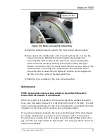
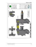
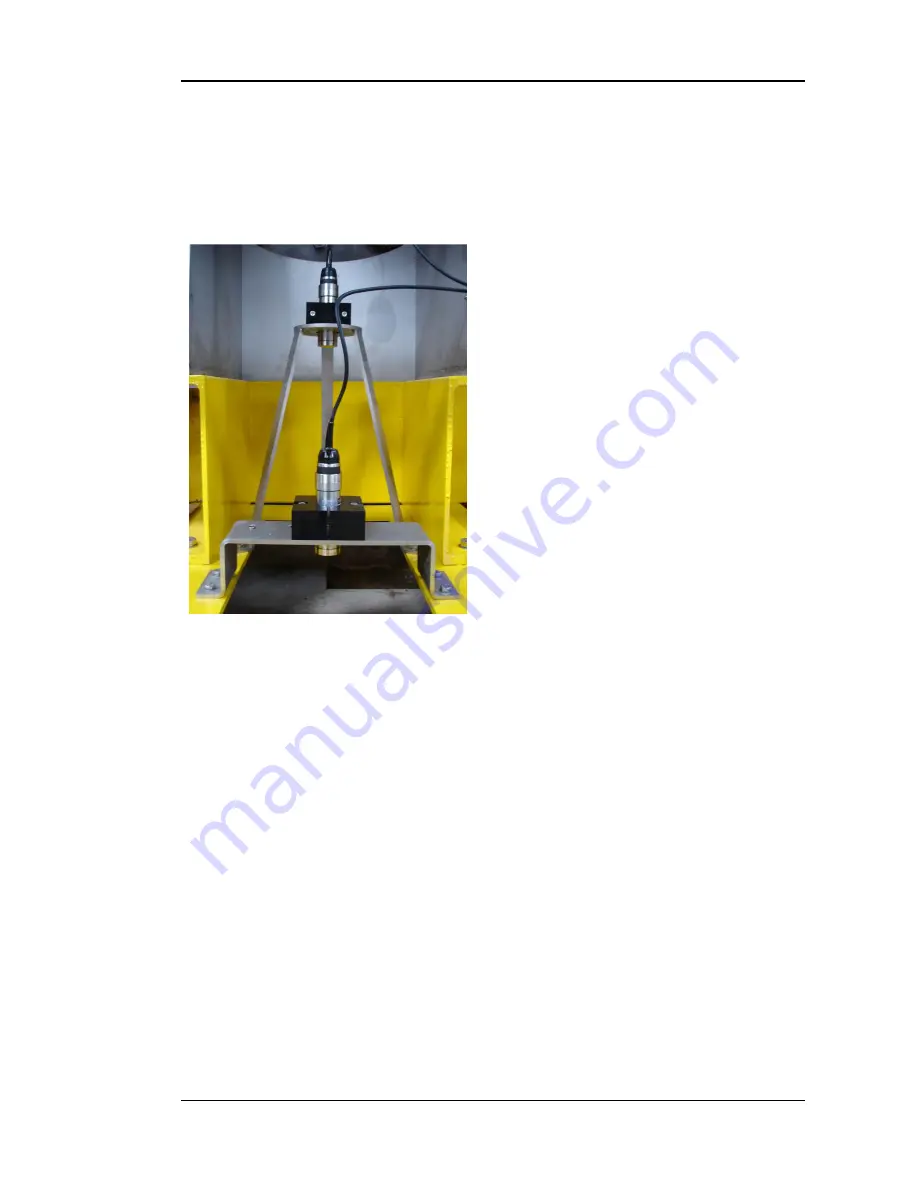
Figure 47: 100m and 10m
Altimeter
Altimeter Assembly
Description
The altimeters are used in two different ways within the system. A 100m
altimeter operates continuously during deployment, to provide longer-range
information of how far the system is off
the seabed. A 10m altimeter operates
at the same time for close range
indication of the approaching seabed. In
addition, the 10m altimeter continues to
send data during the operation of the
system on the seabed, in order to
monitor any sinkage with respect to the
surrounding soil.
Data is transmitted from the sensors
using RS232 protocols, when
individually addressed under software
interrogation.
Specification
Dimensions approx.
170mm x
∅
47mm
Communication
Addressed RS232
Supply Voltage
12Vdc
Maximum Operating Depth
4000m
Configuration
100m – 200kHz/20
°
,
10m – 500kHz/6
°
.
Assembly
There is no exploded view of the altimeters, as there are no user serviceable
parts used. Any damage to these units requires return to Datem for
assessment.
Operational information
It is important to ensure that the correct o-rings have been fitted to the
connectors on the end of the altimeter housing, and that the securing screws
Содержание Neptune 5000
Страница 1: ...Neptune 5000 Copyright Datem Limited 2014 1 Neptune 5000 Technical Manual ...
Страница 14: ...Technical Manual 14 Figure 3 Topside Control Box Wiring Schematic ...
Страница 15: ...Neptune 5000 Copyright Datem Limited 2014 15 Figure 4 Topside Control Box Wiring Layout ...
Страница 30: ...Technical Manual 30 ...
Страница 32: ...Technical Manual 32 Figure 14 Transformer Pod General Arrangement ...
Страница 36: ...Technical Manual 36 Figure 15 Transformer Pod Schematic ...
Страница 39: ...Neptune 5000 Copyright Datem Limited 2014 39 Figure 16 Electronics Pod General Arrangement ...
Страница 44: ...Technical Manual 44 Figure 19 Neptune 5000 Electronics Pod Wiring Schematic ...
Страница 51: ...Neptune 5000 Copyright Datem Limited 2014 51 Figure 23 Inverter Pod General Arrangement ...
Страница 52: ...Technical Manual 52 Figure 24 Inverter Pod Assembly ...
Страница 55: ...Neptune 5000 Copyright Datem Limited 2014 55 Figure 25 Inverter Pod Wiring Schematic ...
Страница 57: ...Neptune 5000 Copyright Datem Limited 2014 57 Figure 26 Inverter Function Settings ...
Страница 62: ...Technical Manual 62 Figure 27 Thruster General Assembly ...
Страница 63: ...Neptune 5000 Copyright Datem Limited 2014 63 Figure 28 Thruster Backplate and Driver Assembly ...
Страница 64: ...Technical Manual 64 Figure 29 Thruster Drum and Cassette Assembly ...
Страница 68: ...Technical Manual 68 ...
Страница 70: ...Technical Manual 70 Figure 30 Thruster Straightener Assembly ...
Страница 77: ...Neptune 5000 Copyright Datem Limited 2014 77 Figure 34 5cm2 Digital Cone Assembly ...
Страница 78: ...Technical Manual 78 Figure 35 10cm2 Digital Cone Assembly ...
Страница 90: ...Technical Manual 90 ...
Страница 91: ...Neptune 5000 Copyright Datem Limited 2014 91 Figure 45 Encoder Parts Drawing ...
Страница 95: ...Neptune 5000 Copyright Datem Limited 2014 95 ...
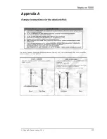
Страница 101: ...Neptune 5000 Copyright Datem Limited 2014 101 Appendix A Sample instructions for the wirelock kit ...
Страница 102: ...Technical Manual 102 ...
Страница 104: ...Technical Manual 104 ...
Страница 105: ...Neptune 5000 Copyright Datem Limited 2014 105 ...
Страница 106: ...Technical Manual 106 ...
Страница 107: ...Neptune 5000 Copyright Datem Limited 2014 107 ...
Страница 108: ...Technical Manual 108 ...
Страница 110: ...Technical Manual 110 ...
Страница 111: ...Neptune 5000 Copyright Datem Limited 2014 111 ...
Страница 112: ...Technical Manual 112 ...
Страница 113: ...Neptune 5000 Copyright Datem Limited 2014 113 ...
Страница 115: ...Neptune 5000 Copyright Datem Limited 2014 115 ...
Страница 116: ...Technical Manual 116 ...
Страница 117: ...Neptune 5000 Copyright Datem Limited 2014 117 ...

