Neptune 5000
© Copyright Datem Limited 2014
17
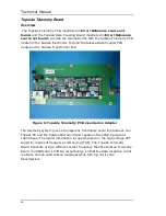
The Power Supply Circuitry pr15Vdc, -15Vdc, +5Vdc, -5Vdc and 0V.
The +/-15Vdc and 0V is used to power the Topside Telemetry Board and the
+/-5Vdc and 0V is used to power the sensing circuits and the LCD displays.
Green LED indicators show the status of the four dc voltages. During normal
operation all four indicators will be illuminated. If any are not illuminated this
is indicative of a fault and the Topside Control Box should be switched off. The
fault should be investigated and rectified before switching on the Topside
Control Box.
The Current Sensing Circuit consists of a current sensing transformer (CT1)
and amplification stage. The ammeter signals are output on PL6, and PL8
provides the +/-5Vdc power to the ammeter display.
The High Voltage output from TXF1 connects to the Topside Power Supply
Board on connector PL3. It then passes through the high voltage sensing
circuitry and then exits the board on PL4. The high voltage sensing circuit
comprises a divider network, isolating transformer (TR1) and a bridge rectifier.
The voltmeter signals are output on PL5, and PL7 provides the +/-5Vdc power.
The Topside Power Supply Board has only one fuse, FU1. This provides
protection for the power supply components only. If this fuse blows this is
indicative of a fault and the Topside Control Box should be switched off. The
fault should be investigated and rectified before switching on the Topside
Control Box.
WARNING
Whenever the Topside control box is switched on the Topside Power
Supply Board could have both 240vac and 650vac on various exposed
components
Specification
Supply Input
240Vac
+/- 10%
Supply Input Current
500mA
Low Voltage Outputs
+/- 15Vdc, +/- 5Vdc
Fuse ratings
FS1: 1A
Содержание Neptune 5000
Страница 1: ...Neptune 5000 Copyright Datem Limited 2014 1 Neptune 5000 Technical Manual ...
Страница 14: ...Technical Manual 14 Figure 3 Topside Control Box Wiring Schematic ...
Страница 15: ...Neptune 5000 Copyright Datem Limited 2014 15 Figure 4 Topside Control Box Wiring Layout ...
Страница 30: ...Technical Manual 30 ...
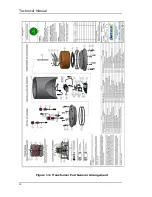
Страница 32: ...Technical Manual 32 Figure 14 Transformer Pod General Arrangement ...
Страница 36: ...Technical Manual 36 Figure 15 Transformer Pod Schematic ...
Страница 39: ...Neptune 5000 Copyright Datem Limited 2014 39 Figure 16 Electronics Pod General Arrangement ...
Страница 44: ...Technical Manual 44 Figure 19 Neptune 5000 Electronics Pod Wiring Schematic ...
Страница 51: ...Neptune 5000 Copyright Datem Limited 2014 51 Figure 23 Inverter Pod General Arrangement ...
Страница 52: ...Technical Manual 52 Figure 24 Inverter Pod Assembly ...
Страница 55: ...Neptune 5000 Copyright Datem Limited 2014 55 Figure 25 Inverter Pod Wiring Schematic ...
Страница 57: ...Neptune 5000 Copyright Datem Limited 2014 57 Figure 26 Inverter Function Settings ...
Страница 62: ...Technical Manual 62 Figure 27 Thruster General Assembly ...
Страница 63: ...Neptune 5000 Copyright Datem Limited 2014 63 Figure 28 Thruster Backplate and Driver Assembly ...
Страница 64: ...Technical Manual 64 Figure 29 Thruster Drum and Cassette Assembly ...
Страница 68: ...Technical Manual 68 ...
Страница 70: ...Technical Manual 70 Figure 30 Thruster Straightener Assembly ...
Страница 77: ...Neptune 5000 Copyright Datem Limited 2014 77 Figure 34 5cm2 Digital Cone Assembly ...
Страница 78: ...Technical Manual 78 Figure 35 10cm2 Digital Cone Assembly ...
Страница 90: ...Technical Manual 90 ...
Страница 91: ...Neptune 5000 Copyright Datem Limited 2014 91 Figure 45 Encoder Parts Drawing ...
Страница 95: ...Neptune 5000 Copyright Datem Limited 2014 95 ...
Страница 101: ...Neptune 5000 Copyright Datem Limited 2014 101 Appendix A Sample instructions for the wirelock kit ...
Страница 102: ...Technical Manual 102 ...
Страница 104: ...Technical Manual 104 ...
Страница 105: ...Neptune 5000 Copyright Datem Limited 2014 105 ...
Страница 106: ...Technical Manual 106 ...
Страница 107: ...Neptune 5000 Copyright Datem Limited 2014 107 ...
Страница 108: ...Technical Manual 108 ...
Страница 110: ...Technical Manual 110 ...
Страница 111: ...Neptune 5000 Copyright Datem Limited 2014 111 ...
Страница 112: ...Technical Manual 112 ...
Страница 113: ...Neptune 5000 Copyright Datem Limited 2014 113 ...
Страница 115: ...Neptune 5000 Copyright Datem Limited 2014 115 ...
Страница 116: ...Technical Manual 116 ...
Страница 117: ...Neptune 5000 Copyright Datem Limited 2014 117 ...


