Neptune 5000
© Copyright Datem Limited 2014
71
Operational Information
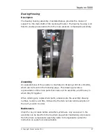
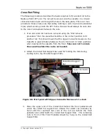
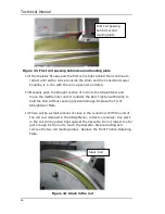
When removing a cone-rod, it is necessary to release the tension in the
straightener, and remove its front reinforcing plate to allow the cone-rod easy
exit. To do this, follow the instruction listed below.
1.
Remove the cone from the end of the coiled rod, taking great care
when the threads are undone to ease the cone and coiled rod apart
to gain access to the connector inside, easing this apart without
damaging the wires.
2.
Loosen the lock nuts fitted to the roller adjuster bolt, protruding
from the side of the straightener, approximately one turn.
3.
Loosen the roller adjuster bolt, and screw it out as far as it will
move.
4.
Remove the four nuts holding the front reinforcing plate on, remove
the plate, and then loosely refit the nuts to prevent accidental loss.
5.
Loosen the four cap bolts that hold the scraper blocks on the bottom
of the straightener, slide the blocks out as far as they will move, and
retighten the bolts by hand to prevent accidental movement.
6.
The rod can now be pulled out of the gap between the rollers.
When refitting a cone-rod, the above procedure can be followed in reverse
order, but before the final operation of tightening the lock nuts, the
straightener must be correctly adjusted, as discussed below.
Straightener Adjustment
Whenever a new rod is fitted it is necessary to reset the tension of the
adjustable roller in the straightener assembly. For this operation the unit
needs to be raised to allow a 1-1.5m push of coiled rod to be pushed out,
where it can be observed for straightness. It is possible to set up the
straightener using either the manual inverter, or the main system.
Warning:
If the main system is to be used, the operator should have direct
view of the operation from the controlling computer, and the
maximum push distance set to less than the raised height. Using the
manual inverter requires special care as this removes all safety
features of the operating software.
The procedure below should be followed for setting the straightener.
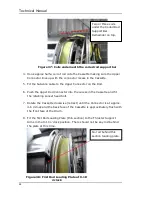
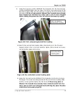
1.
Tighten the adjustable roller by hand, until it is in contact with the
cone-rod.
Содержание Neptune 5000
Страница 1: ...Neptune 5000 Copyright Datem Limited 2014 1 Neptune 5000 Technical Manual ...
Страница 14: ...Technical Manual 14 Figure 3 Topside Control Box Wiring Schematic ...
Страница 15: ...Neptune 5000 Copyright Datem Limited 2014 15 Figure 4 Topside Control Box Wiring Layout ...
Страница 30: ...Technical Manual 30 ...
Страница 32: ...Technical Manual 32 Figure 14 Transformer Pod General Arrangement ...
Страница 36: ...Technical Manual 36 Figure 15 Transformer Pod Schematic ...
Страница 39: ...Neptune 5000 Copyright Datem Limited 2014 39 Figure 16 Electronics Pod General Arrangement ...
Страница 44: ...Technical Manual 44 Figure 19 Neptune 5000 Electronics Pod Wiring Schematic ...
Страница 51: ...Neptune 5000 Copyright Datem Limited 2014 51 Figure 23 Inverter Pod General Arrangement ...
Страница 52: ...Technical Manual 52 Figure 24 Inverter Pod Assembly ...
Страница 55: ...Neptune 5000 Copyright Datem Limited 2014 55 Figure 25 Inverter Pod Wiring Schematic ...
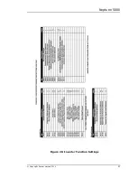
Страница 57: ...Neptune 5000 Copyright Datem Limited 2014 57 Figure 26 Inverter Function Settings ...
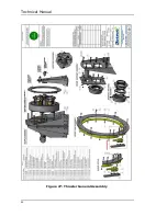
Страница 62: ...Technical Manual 62 Figure 27 Thruster General Assembly ...
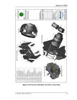
Страница 63: ...Neptune 5000 Copyright Datem Limited 2014 63 Figure 28 Thruster Backplate and Driver Assembly ...
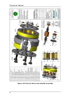
Страница 64: ...Technical Manual 64 Figure 29 Thruster Drum and Cassette Assembly ...
Страница 68: ...Technical Manual 68 ...
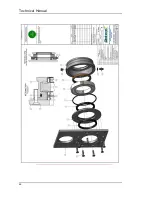
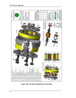
Страница 70: ...Technical Manual 70 Figure 30 Thruster Straightener Assembly ...
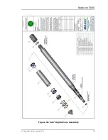
Страница 77: ...Neptune 5000 Copyright Datem Limited 2014 77 Figure 34 5cm2 Digital Cone Assembly ...
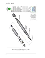
Страница 78: ...Technical Manual 78 Figure 35 10cm2 Digital Cone Assembly ...
Страница 90: ...Technical Manual 90 ...
Страница 91: ...Neptune 5000 Copyright Datem Limited 2014 91 Figure 45 Encoder Parts Drawing ...
Страница 95: ...Neptune 5000 Copyright Datem Limited 2014 95 ...
Страница 101: ...Neptune 5000 Copyright Datem Limited 2014 101 Appendix A Sample instructions for the wirelock kit ...
Страница 102: ...Technical Manual 102 ...
Страница 104: ...Technical Manual 104 ...
Страница 105: ...Neptune 5000 Copyright Datem Limited 2014 105 ...
Страница 106: ...Technical Manual 106 ...
Страница 107: ...Neptune 5000 Copyright Datem Limited 2014 107 ...
Страница 108: ...Technical Manual 108 ...
Страница 110: ...Technical Manual 110 ...
Страница 111: ...Neptune 5000 Copyright Datem Limited 2014 111 ...
Страница 112: ...Technical Manual 112 ...
Страница 113: ...Neptune 5000 Copyright Datem Limited 2014 113 ...
Страница 115: ...Neptune 5000 Copyright Datem Limited 2014 115 ...
Страница 116: ...Technical Manual 116 ...
Страница 117: ...Neptune 5000 Copyright Datem Limited 2014 117 ...

