Technical Manual
34
Pod Refitting
Refitting the pod is simply the reverse process of removal, but special care should be
taken with ensuring that the threads on the clamp are in good condition, and that
anti-seize grease is applied to the threads of the clamp to avoid galling.
Pod Top-Cap Removal
To remove the top-cap assembly:
1.
Firstly ensure the power is removed from the system, and
appropriate action is taken to prevent accidental energisation,
2.
Remove all the cables from the pod’s connectors, and fit dummy
connectors, caps or other appropriate cover to the connectors,
3.
Remove the M6 cap bolts from around the top-cap,
4.
Fit two of the M6x35 cap bolts to the jacking holes, and
systematically turn them, jacking the entire top-cap out of the
vessel,
5.
Due to the weight of the top-cap, appropriate lifting apparatus
should be used to carefully lift the top-cap until there is a gap of
approximately 100mm between the cap and the vessel,
6.
Place lifting blocks between the top-cap and vessel in case of
lifting apparatus failure, leaving sufficient space for access by
hand,
7.
Disconnect all the in-line cable connectors that attach the top-cap
to the internal equipment,
8.
Slowly remove the cap, ensuring that no cables have snagged,
and place upside down on a suitable Topside to prevent connector
damage,
9.
If the top-cap is removed with the pod outside, place an
appropriate blanking plate over the open vessel to keep any
water out. It should be noted that the pod should not be left like
this outside for very long due to the high risk of moisture ingress.
Pod Top-Cap Refitting
Refitting the top-cap is simply the reverse process of removal, but special care
should be taken with ensuring the o-rings are in good condition and lightly
lubricated with silicone grease.
Pod Lower Cap Removal
It is not necessary to remove the lower cap of the pod for the majority of work
undertaken. It is however necessary if the transformer requires replacement.
Disassembly should only be carried out in a dry workshop environment. Refer
to section 6.3.1 Pod Removal in order to get the pod removed to the working
environment. The following procedure should be followed to remove the lower
Содержание Neptune 5000
Страница 1: ...Neptune 5000 Copyright Datem Limited 2014 1 Neptune 5000 Technical Manual ...
Страница 14: ...Technical Manual 14 Figure 3 Topside Control Box Wiring Schematic ...
Страница 15: ...Neptune 5000 Copyright Datem Limited 2014 15 Figure 4 Topside Control Box Wiring Layout ...
Страница 30: ...Technical Manual 30 ...
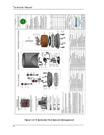
Страница 32: ...Technical Manual 32 Figure 14 Transformer Pod General Arrangement ...
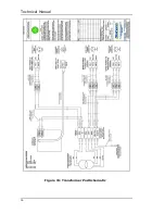
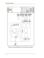
Страница 36: ...Technical Manual 36 Figure 15 Transformer Pod Schematic ...
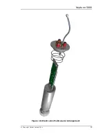
Страница 39: ...Neptune 5000 Copyright Datem Limited 2014 39 Figure 16 Electronics Pod General Arrangement ...
Страница 44: ...Technical Manual 44 Figure 19 Neptune 5000 Electronics Pod Wiring Schematic ...
Страница 51: ...Neptune 5000 Copyright Datem Limited 2014 51 Figure 23 Inverter Pod General Arrangement ...
Страница 52: ...Technical Manual 52 Figure 24 Inverter Pod Assembly ...
Страница 55: ...Neptune 5000 Copyright Datem Limited 2014 55 Figure 25 Inverter Pod Wiring Schematic ...
Страница 57: ...Neptune 5000 Copyright Datem Limited 2014 57 Figure 26 Inverter Function Settings ...
Страница 62: ...Technical Manual 62 Figure 27 Thruster General Assembly ...
Страница 63: ...Neptune 5000 Copyright Datem Limited 2014 63 Figure 28 Thruster Backplate and Driver Assembly ...
Страница 64: ...Technical Manual 64 Figure 29 Thruster Drum and Cassette Assembly ...
Страница 68: ...Technical Manual 68 ...
Страница 70: ...Technical Manual 70 Figure 30 Thruster Straightener Assembly ...
Страница 77: ...Neptune 5000 Copyright Datem Limited 2014 77 Figure 34 5cm2 Digital Cone Assembly ...
Страница 78: ...Technical Manual 78 Figure 35 10cm2 Digital Cone Assembly ...
Страница 90: ...Technical Manual 90 ...
Страница 91: ...Neptune 5000 Copyright Datem Limited 2014 91 Figure 45 Encoder Parts Drawing ...
Страница 95: ...Neptune 5000 Copyright Datem Limited 2014 95 ...
Страница 101: ...Neptune 5000 Copyright Datem Limited 2014 101 Appendix A Sample instructions for the wirelock kit ...
Страница 102: ...Technical Manual 102 ...
Страница 104: ...Technical Manual 104 ...
Страница 105: ...Neptune 5000 Copyright Datem Limited 2014 105 ...
Страница 106: ...Technical Manual 106 ...
Страница 107: ...Neptune 5000 Copyright Datem Limited 2014 107 ...
Страница 108: ...Technical Manual 108 ...
Страница 110: ...Technical Manual 110 ...
Страница 111: ...Neptune 5000 Copyright Datem Limited 2014 111 ...
Страница 112: ...Technical Manual 112 ...
Страница 113: ...Neptune 5000 Copyright Datem Limited 2014 113 ...
Страница 115: ...Neptune 5000 Copyright Datem Limited 2014 115 ...
Страница 116: ...Technical Manual 116 ...
Страница 117: ...Neptune 5000 Copyright Datem Limited 2014 117 ...

