Neptune 5000
© Copyright Datem Limited 2014
67
Bearing Housing
Description
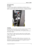
The bearing housing assembly, illustrated below, provides the means of
support for the main shaft of the revolving thruster. The bearing housing is oil
filled to enable pressurisation from the main pressure compensator assembly.
Assembly
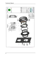
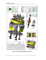
An exploded view of the encoder is illustrated in Drawing 1443-01-103-ASS,
which can be found on the following page. This drawing provides a
representation of the main parts that make up the assembly, and the way in
which they fit together.
When ordering any replacement parts, please quote the assembly drawing
number, revision, and title, followed by the item number and description of
the part you wish to order.
Maintenance
Check for any oil leaks before and after system use. Any excess air in the
assembly can be bled from the top drain plug whilst maintaining oil pressure
from the main compensator assembly. Refer to Compensator section for
instruction on system oil pressurisation.
Содержание Neptune 5000
Страница 1: ...Neptune 5000 Copyright Datem Limited 2014 1 Neptune 5000 Technical Manual ...
Страница 14: ...Technical Manual 14 Figure 3 Topside Control Box Wiring Schematic ...
Страница 15: ...Neptune 5000 Copyright Datem Limited 2014 15 Figure 4 Topside Control Box Wiring Layout ...
Страница 30: ...Technical Manual 30 ...
Страница 32: ...Technical Manual 32 Figure 14 Transformer Pod General Arrangement ...
Страница 36: ...Technical Manual 36 Figure 15 Transformer Pod Schematic ...
Страница 39: ...Neptune 5000 Copyright Datem Limited 2014 39 Figure 16 Electronics Pod General Arrangement ...
Страница 44: ...Technical Manual 44 Figure 19 Neptune 5000 Electronics Pod Wiring Schematic ...
Страница 51: ...Neptune 5000 Copyright Datem Limited 2014 51 Figure 23 Inverter Pod General Arrangement ...
Страница 52: ...Technical Manual 52 Figure 24 Inverter Pod Assembly ...
Страница 55: ...Neptune 5000 Copyright Datem Limited 2014 55 Figure 25 Inverter Pod Wiring Schematic ...
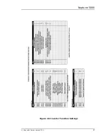
Страница 57: ...Neptune 5000 Copyright Datem Limited 2014 57 Figure 26 Inverter Function Settings ...
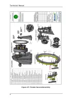
Страница 62: ...Technical Manual 62 Figure 27 Thruster General Assembly ...
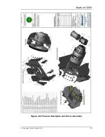
Страница 63: ...Neptune 5000 Copyright Datem Limited 2014 63 Figure 28 Thruster Backplate and Driver Assembly ...
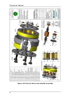
Страница 64: ...Technical Manual 64 Figure 29 Thruster Drum and Cassette Assembly ...
Страница 68: ...Technical Manual 68 ...
Страница 70: ...Technical Manual 70 Figure 30 Thruster Straightener Assembly ...
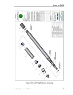
Страница 77: ...Neptune 5000 Copyright Datem Limited 2014 77 Figure 34 5cm2 Digital Cone Assembly ...
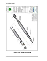
Страница 78: ...Technical Manual 78 Figure 35 10cm2 Digital Cone Assembly ...
Страница 90: ...Technical Manual 90 ...
Страница 91: ...Neptune 5000 Copyright Datem Limited 2014 91 Figure 45 Encoder Parts Drawing ...
Страница 95: ...Neptune 5000 Copyright Datem Limited 2014 95 ...
Страница 101: ...Neptune 5000 Copyright Datem Limited 2014 101 Appendix A Sample instructions for the wirelock kit ...
Страница 102: ...Technical Manual 102 ...
Страница 104: ...Technical Manual 104 ...
Страница 105: ...Neptune 5000 Copyright Datem Limited 2014 105 ...
Страница 106: ...Technical Manual 106 ...
Страница 107: ...Neptune 5000 Copyright Datem Limited 2014 107 ...
Страница 108: ...Technical Manual 108 ...
Страница 110: ...Technical Manual 110 ...
Страница 111: ...Neptune 5000 Copyright Datem Limited 2014 111 ...
Страница 112: ...Technical Manual 112 ...
Страница 113: ...Neptune 5000 Copyright Datem Limited 2014 113 ...
Страница 115: ...Neptune 5000 Copyright Datem Limited 2014 115 ...
Страница 116: ...Technical Manual 116 ...
Страница 117: ...Neptune 5000 Copyright Datem Limited 2014 117 ...

