Technical Manual
48
The telemetry system gives a transparent, full duplex serial link between the
Subsea Microcontroller Board and the Topside PC capable of transferring data
at 19200 baud.
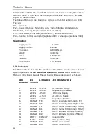
LED Indicators
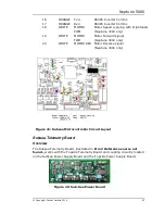
Seven LED indicators are fitted to the Subsea Telemetry Board. Three green
LEDs show the power supply status: “+15V” and “-15V” are generated by the
Subsea Power Supply Board, while “+5V” is derived from the +15V supply by
an on-board voltage regulator. Four yellow LEDs monitor communications
activity: “Rx0” is illuminated whenever a character is received from the
Subsea Microcontroller Board; “Tx0” when a character is transmitted to the
Subsea Microcontroller Board; “Tx1” when a character is transmitted to the
Topside Telemetry Board; “Rx1” when a character is received from the Topside
Telemetry Board.
Automatic Tuning
The automatic telemetry tuning sequence takes approximately 5 seconds if
both telemetry boards are active and there are no hardware faults. During
tuning, the “Tx1” LED is illuminated, while the “Rx1” LED turns on and off at
about 1 second intervals. Once two-way communication has been established,
both “Tx1” and “Rx1” will blink very rapidly at about equal intensity, showing
that handshake messages are being transmitted and received.
Maintenance
NOTE:
Appropriate safe working practices should be followed to ensure
that all hazards are minimised.
When the system is in operation, the Electronics Pod should be washed down
with clean, salt-free water whenever it is returned to the deck of the vessel.
This will reduce corrosion, and enable thorough inspection of all the main
housing, connectors, and connecting cables.
Where the pod is disassembled, all the o-rings should be checked to ensure
that none of them are damaged. It is recommended during reassembly, to use
a small amount of silicone grease on the o-rings to prevent chafing.
It is good working practice to regularly check all fastenings to ensure they are
present, tight, and there is no damage to them or the items they are fitted to.
Any damaged fastenings should be replaced immediately.
Содержание Neptune 5000
Страница 1: ...Neptune 5000 Copyright Datem Limited 2014 1 Neptune 5000 Technical Manual ...
Страница 14: ...Technical Manual 14 Figure 3 Topside Control Box Wiring Schematic ...
Страница 15: ...Neptune 5000 Copyright Datem Limited 2014 15 Figure 4 Topside Control Box Wiring Layout ...
Страница 30: ...Technical Manual 30 ...
Страница 32: ...Technical Manual 32 Figure 14 Transformer Pod General Arrangement ...
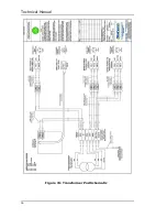
Страница 36: ...Technical Manual 36 Figure 15 Transformer Pod Schematic ...
Страница 39: ...Neptune 5000 Copyright Datem Limited 2014 39 Figure 16 Electronics Pod General Arrangement ...
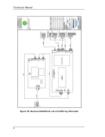
Страница 44: ...Technical Manual 44 Figure 19 Neptune 5000 Electronics Pod Wiring Schematic ...
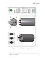
Страница 51: ...Neptune 5000 Copyright Datem Limited 2014 51 Figure 23 Inverter Pod General Arrangement ...
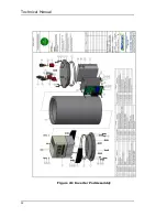
Страница 52: ...Technical Manual 52 Figure 24 Inverter Pod Assembly ...
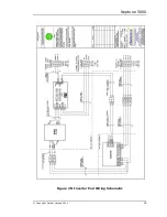
Страница 55: ...Neptune 5000 Copyright Datem Limited 2014 55 Figure 25 Inverter Pod Wiring Schematic ...
Страница 57: ...Neptune 5000 Copyright Datem Limited 2014 57 Figure 26 Inverter Function Settings ...
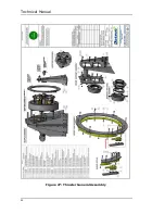
Страница 62: ...Technical Manual 62 Figure 27 Thruster General Assembly ...
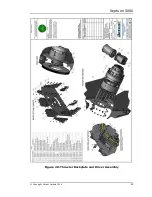
Страница 63: ...Neptune 5000 Copyright Datem Limited 2014 63 Figure 28 Thruster Backplate and Driver Assembly ...
Страница 64: ...Technical Manual 64 Figure 29 Thruster Drum and Cassette Assembly ...
Страница 68: ...Technical Manual 68 ...
Страница 70: ...Technical Manual 70 Figure 30 Thruster Straightener Assembly ...
Страница 77: ...Neptune 5000 Copyright Datem Limited 2014 77 Figure 34 5cm2 Digital Cone Assembly ...
Страница 78: ...Technical Manual 78 Figure 35 10cm2 Digital Cone Assembly ...
Страница 90: ...Technical Manual 90 ...
Страница 91: ...Neptune 5000 Copyright Datem Limited 2014 91 Figure 45 Encoder Parts Drawing ...
Страница 95: ...Neptune 5000 Copyright Datem Limited 2014 95 ...
Страница 101: ...Neptune 5000 Copyright Datem Limited 2014 101 Appendix A Sample instructions for the wirelock kit ...
Страница 102: ...Technical Manual 102 ...
Страница 104: ...Technical Manual 104 ...
Страница 105: ...Neptune 5000 Copyright Datem Limited 2014 105 ...
Страница 106: ...Technical Manual 106 ...
Страница 107: ...Neptune 5000 Copyright Datem Limited 2014 107 ...
Страница 108: ...Technical Manual 108 ...
Страница 110: ...Technical Manual 110 ...
Страница 111: ...Neptune 5000 Copyright Datem Limited 2014 111 ...
Страница 112: ...Technical Manual 112 ...
Страница 113: ...Neptune 5000 Copyright Datem Limited 2014 113 ...
Страница 115: ...Neptune 5000 Copyright Datem Limited 2014 115 ...
Страница 116: ...Technical Manual 116 ...
Страница 117: ...Neptune 5000 Copyright Datem Limited 2014 117 ...

