8
Where applicable, the method of immobilisation for the machine should be selected and the wiring configured accordingly.
The methods available are shown in annex 4
at the rear of this manual.
Access the wiring harness at the most suitable place(s) and identify the wires you are going to connect to using suitable
safe test equipment.
Analogue meters and bulb based test lights are LOW resistance and can easily damage delicate electronic units fitted to
some machines.
It is advisable to use HIGH resistance test equipment (e.g. Digital multi-meters, LED based test lights {logic probes}, LCD
testers).
If you have doubts regarding the suitability of your test equipment, please refer to the manufacturer’s workshop manual.
Once the alarm wiring points have been selected, construct the alarm harness accordingly. When constructing the alarm
loom pay close attention to the positioning of the alarm plugs in relation to each other. It is advisable to temporarily
connect the alarm harness to the alarm at this stage to correctly align and tape or heat shrink the harness together whilst
constructing the harness. Failure to do this may mean the plugs cannot be easily connected between the alarm and the
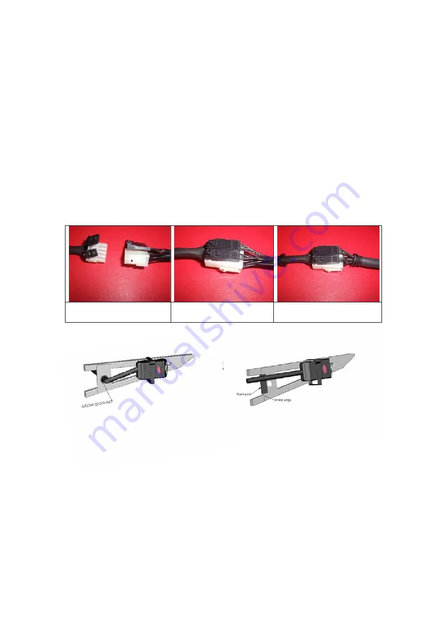
harness. Please notice the alignment of the plugs in the diagram below, the harness should be constructed so the FLAT
sides of the plugs are placed together (i.e. clasps outwards).
Alarm plugs and harness
disconnected
Alarm plugs connected
Alarm plugs connected and loom
taped or heat shrunk to lock the plug
positions
When routing the alarm harness it is wise to run it alongside or within the original wiring harness of the machine and
loom/sleeve it in a similar manner to the original harness where possible. The loom must be protected from any sharp
edges likely to cause damage to the harness.
Once the positions have been fixed, the alarm loom should be disconnected from the alarm and transferred to the
installation test box.
Always use the installation test box to further verify the connection. It is good practice to carry out a stage and then test
that stage via the test box before going to the next.
Connection methods
Soldered joints are recommended for all wiring connections, protected by a suitable insulation technique (heat shrink or
good quality insulation tape, correctly applied). Where connectors are used, they must be to at least the same standard
as the machine’s original equipment. Insulation displacement connectors (Scotchloks) must not be used under any
circumstances.
If a wire is not being used (e.g. secondary trigger, siren wire, etc) but may be required at some future date, the wire
should be fully insulated with its tags visible and secured safely at a convenient position. The position should be noted on
the certificate of installation.
Wires not required/not needed in the future are best removed from the harness completely or cut and correctly insulated.


