


Removal and Replacement
4-29
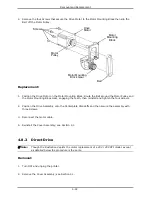
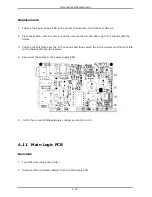
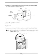
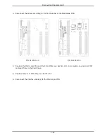
2. Insert the Main Logic PCB between the Guides in the Card Cage then slide it forward until seated.
3. Reinstall the two previously removed screws and secure the Main Logic PCB in the Card Cage.
4. Reinstall the interface cable(s).
5. Verify the installed Application Version for the printer model; see Section 2.6.
6. Configure the printer; see the Operator’s Manual for details.
7. Perform calibration; see Section 2.1
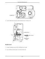
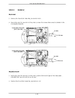
4.12 Backplane PCB
Removal:
1. Turn OFF and unplug the printer.
2. Disconnect the interface cable(s) from the Main Logic PCB.
3. Remove the Cover Assembly; see Section 4.1.
4. Remove the Main Logic PCB and the Filler Plate; see Section 4.11. Also remove any other
optional PCB installed in the Card Cage.
5. Disconnect the cables from the Backplane PCB.
Содержание I-Class
Страница 1: ...I Maintenance Manual...
Страница 3: ...i Contents 1 Overview 2 Adjustments and Maintenance 3 Troubleshooting 4 Removal and Replacement...
Страница 4: ...ii...
Страница 5: ...i 1 Overview 1 0 Introduction 1 1 1 About the Printer 2...
Страница 6: ...ii...
Страница 38: ...ii...
Страница 56: ...ii 4 11 Main Logic PCB 27 4 12 Backplane PCB 29...