


Removal and Replacement
4-31
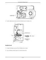
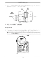
If installing P/N 51-2348-00, configure
the settings of the Jumpers according to
the equipped options and default
requirements:
•
Scanner equipped: E1 & E2, E5 &
E6;
•
RFID equipped: E2 & E3, E4 & E4;
•
COM2 DTR Active (default): E7 & E8;
and,
•
Ribbon Motion (default): E11 & E12.
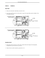
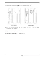
2. Place the Backplane PCB into the Card Cage and then secure it with the four Screws.
Screws
Backplane
PCB
Card
Cage
Содержание I-Class
Страница 1: ...I Maintenance Manual...
Страница 3: ...i Contents 1 Overview 2 Adjustments and Maintenance 3 Troubleshooting 4 Removal and Replacement...
Страница 4: ...ii...
Страница 5: ...i 1 Overview 1 0 Introduction 1 1 1 About the Printer 2...
Страница 6: ...ii...
Страница 38: ...ii...
Страница 56: ...ii 4 11 Main Logic PCB 27 4 12 Backplane PCB 29...


