SET UP
48
VLASE™ IR
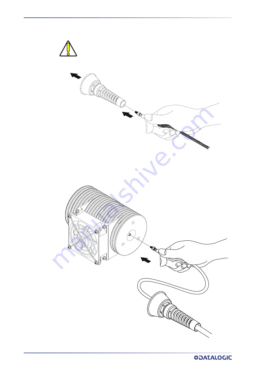
2. insert the optical fiber through the cable gland without removing the protection
cap.
Figure 12: Passing the optical fiber through the cable gland
3. remove the protection cap and insert the optical fiber in the resonator, being care-
ful not to soil or scratch the fiber end. Tighten the hexagonal nut of the fiber by
hand, until resistance to rotation is felt.
Figure 13: Connecting the optical fiber to resonator.
CAUTION
The insertion of the optical fiber is a delicate operation. You must
make sure that the optical fiber is protected by its cap during inser-
tion through the cable gland to avoid damaging or dirtying it.
Содержание VLASE IR 1109-1 42 Series
Страница 1: ...VLASE IR USER MANUAL InfraRed Laser Marker ...
Страница 72: ...USE AND OPERATION 64 VLASE IR ...
Страница 98: ...LABELS 90 VLASE IR Positioning of labels on the resonator Figure 2 External labels rsonator location ...
Страница 101: ...PERFORMANCE LEVEL PL USER MANUAL 93 BLOCK DIAGRAM ...
Страница 121: ...THERMALIZATION AND SUPPRESSION OF GIANT PULSES USER MANUAL 113 ...
Страница 133: ...USER MANUAL 125 APPENDIX G MECHANICAL DRAWINGS ...
Страница 134: ...MECHANICAL DRAWINGS 126 VLASE IR CONTROL RACK NOTE Please refer to Datalogic website for detailed drawings ...
Страница 135: ...RESONATOR USER MANUAL 127 RESONATOR NOTE Please refer to Datalogic website for detailed drawings ...


