Overview
26.04.2005
condition. When a fault/error condition warrants, the truck controller may open the main
contactor, removing battery power from the AC SuperDrive power stage.
2.1 P
RINCIPLES OF OPERATION
2.1.1 B
LOCK DIAGRAM
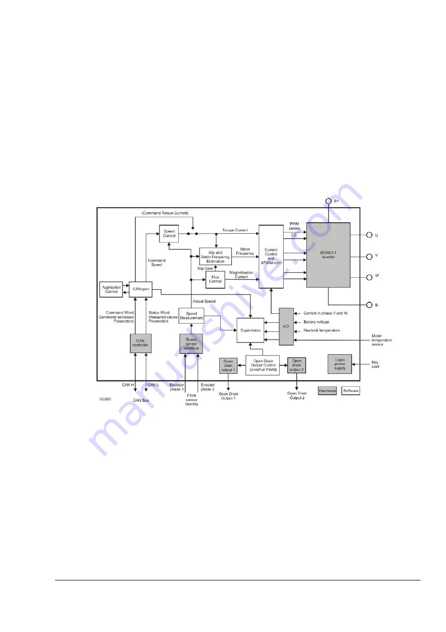
shows a functional block diagram of the AC SuperDrive including the principal drive
inputs and outputs. Some SuperDrive functions are executed by dedicated hardware, while
others are implemented mainly in software. The following paragraphs provide additional details
on each functional block.
Figure 4. AC SuperDrive Block Diagram
2.1.2 CAN
INTERFACE
The CAN Interface manages communications between the AC SuperDrive and the CAN Bus.
The CAN controller provides the electrical interface and within the software the CANopen
protocol is handled.
2.1.3 S
PEED CONTROL
The Speed Control accepts speed set points (Command Speed) as input and produces torque
commands (Torque Current) as output. It can function as a closed loop, proportional or
proportional plus integral, speed controller with feedback provided by the speed encoder. It
includes provisions for limiting torque both in amplitude and derivate. It is also possible to use
Item No.
89Y05120A
User's Guide 1.0
14
Содержание SuperDrive ACS24 Series
Страница 12: ......
Страница 34: ......
Страница 38: ......
Страница 79: ...26 04 2005 Troubleshooting guide User s Guide 1 0 Item No 89Y05120A 79...
Страница 81: ...26 04 2005 Troubleshooting guide User s Guide 1 0 Item No 89Y05120A 81...
Страница 82: ...Troubleshooting guide 26 04 2005 Item No 89Y05120A User s Guide 1 0 82...
Страница 86: ...Troubleshooting guide 26 04 2005 7 7 11 CAN TIME OUT Error Code 0x8100 Item No 89Y05120A User s Guide 1 0 86...
Страница 92: ......


