370 S 370 S L 370 PP 370 PP L
26
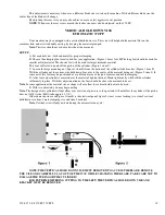
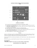
G: On the piece counter, clear out the previous number that has been cut. Press the lower centered button to clear this
number out. See graphic A this page.
H: Enter into the counter the number of parts you need to cut. (If you run out of stock before this amount has been met,
the machine will shut off) See figure B
I: Example: Clear counter. Pressing individual buttons enter the number to be cut which shown here is 632 pieces.
I: Place your material in position for cutting.(If vises are clamped turn off the security key) Move the material
up to the blades path Keep the material as close to this point as possible, this will be your first cut piece.
No face cut
will be made.
K: Switch cycle selector to automatic mode.
L: Switch the vise position switch on lower control panel to backward.
M: Select speed.
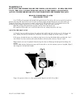
N: Close head feed flow control valve.
O: Check setting on motor protection, that it is set correctly. (If machine does not start check the reset button
on blade protection device.) Turn the security key to the ON posit
P: Press green start button.
There will be a slight delay before machine starts. This is a safety feature built into
the machine.
Q: Adjust head feed flow control.
R: Adjust your coolant flow.
S: Adjust the feeder speeds, forward and backwards.
This allows you to adjust the rate of time it takes to feed the
material in both forward and backward motion.
Do not set this feed rate excessive or damage may occur and
tolerances may slip.
WARNING!!!!!
Make sure head feed control is closed before starting cycle. Head could overfeed into the part if this
is not followed, causing possible blade, or machine damage, or may result in personal injury.
These are the operations that will be carried out.
1. Feeder advances material.
2. Vises clamp part.
3. Motor starts, coolant flow starts and head descends.
4. Part is cut, coolant flow stops. Registers part a 1 piece cut.
5. Head returns to upper preset.
6. Main vise unclamps, feed vise clamps.
7. Feeds material forward and cycle repeats, until preset numbers have been cut or material runs out.
Set up for face cut
Follow the instructions listed above with the exception of material placement and cycle mode and feed vise position settings.
The material must be placed under the blade, the thickness of the face cut wanted. When the cycle starts, the cycle switch must
be in semi-automatic. The feed vise position switch must be set in the forward position. Once the cycle start button has been
pressed, turn the cycle mode switch to the automatic position and the feed vise position switch to the rear position. Now the
machine will complete the automatic program after making your face cut.
Note
: Failure to follow the above procedure may result in the first cut piece being out of tolerance.
OPERATIONAL AND CUTTING TIPS
Blade Tips
A: Always inspect blade before installing on machine. If questionable don't use.
Содержание Euromatic 370 S
Страница 9: ...370 S 370 S L 370 PP 370 PP L 9...
Страница 10: ...370 S 370 S L 370 PP 370 PP L 10 Actual control panel layout may vari...
Страница 32: ...370 S 370 S L 370 PP 370 PP L 32...
Страница 33: ...370 S 370 S L 370 PP 370 PP L 33...
Страница 38: ...ALIMENTAZIONE 230V 60Hz 230V 60Hz POWER SUPPLY POWER SUPPLY...
Страница 39: ...HL4 ILLUMINAZIONE LAMA POWER SUPPLY...
Страница 40: ...LAMPEGGIATORE LAMA IN MOTO 24VAC MORSA 24VAC EMERGENCIES...
Страница 41: ...DISCESA TESTA EV DISCESA TESTA START MEMORIA PULSANTE CICLO SB4 START CICLO ELECTROMECHANICALCIRCUIT...
Страница 44: ...9 11 2 4 5 10 3 6 7 8 1 CH1 LC4HR424ACJ KA5 RITORNO CARRO COUNTER...
Страница 45: ...TERMINAL...
Страница 49: ...10 2 2019 Euromatic 370 2 Head Cylinder Unit Ref 005...
Страница 51: ...10 2 2019 Euromatic 370 4 Bedplate Unit Ref 008...
Страница 53: ...10 2 2019 Euromatic 370 6 Head Unit Ref 002...
Страница 55: ...10 2 2019 Euromatic 370 8 Vise Unit Ref 004...
Страница 57: ...10 2 2019 Euromatic 370 10 Group Feeder P R...
Страница 59: ...10 2 2019 Euromatic 370 12 Group Alimentador P P Ref 014b Alimentador Ref 014b...


