370 S 370 S L 370 PP 370 PP L
15
SETTING THE HEAD PARAMETERS
Warning!!!!!
Never depress the limit switches with your finger. Your finger could be crushed or amputated
between the limit switch and cam block.
Setting the head parameters
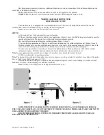
This is quite simple and very dependable method of reducing “dead air” cutting. The above graphic illustrates the four
basic parts of the head positioning system.
A is the lower limit, adjustable cam block.
B. is the machined T-slot way that the cams move vertically in.
C. is the upper head limit, adjustable cam block.
D. is the limit switch that will control the lower setting. When this switch is activated the blade stops and the head
returns to the upper setting.
E. This is the upper limit switch; this controls the head on the return stroke and stops it in the upper setting.
The gear box is on the left, and the vertical column is on the right side, as looking at the adjustments.
To set these parameters move the cams to the extreme positions and snug down. (The top cam up and the lower cam
down)
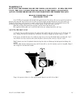
1. Power up the machine, and check that you have air pressure on the gauge.
2. Turn the speed selector switch to the “0” setting.
3. Place material in the main vise, and up to the blades path.
Do not place under the
Blade path.
move the head feed control valve to zero.
4.
Make sure the emergency button is not engaged.
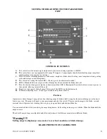
On automatic machines (370 PP) place the cycle selector switch to the
“semi-auto” mode (hand symbol). Press the green cycle button (370S Yellow Button) (370PP push the green button then push
the yellow button) and slowly open the head feed valve. As the head descends downward toward the material, close the head
Содержание Euromatic 370 S
Страница 9: ...370 S 370 S L 370 PP 370 PP L 9...
Страница 10: ...370 S 370 S L 370 PP 370 PP L 10 Actual control panel layout may vari...
Страница 32: ...370 S 370 S L 370 PP 370 PP L 32...
Страница 33: ...370 S 370 S L 370 PP 370 PP L 33...
Страница 38: ...ALIMENTAZIONE 230V 60Hz 230V 60Hz POWER SUPPLY POWER SUPPLY...
Страница 39: ...HL4 ILLUMINAZIONE LAMA POWER SUPPLY...
Страница 40: ...LAMPEGGIATORE LAMA IN MOTO 24VAC MORSA 24VAC EMERGENCIES...
Страница 41: ...DISCESA TESTA EV DISCESA TESTA START MEMORIA PULSANTE CICLO SB4 START CICLO ELECTROMECHANICALCIRCUIT...
Страница 44: ...9 11 2 4 5 10 3 6 7 8 1 CH1 LC4HR424ACJ KA5 RITORNO CARRO COUNTER...
Страница 45: ...TERMINAL...
Страница 49: ...10 2 2019 Euromatic 370 2 Head Cylinder Unit Ref 005...
Страница 51: ...10 2 2019 Euromatic 370 4 Bedplate Unit Ref 008...
Страница 53: ...10 2 2019 Euromatic 370 6 Head Unit Ref 002...
Страница 55: ...10 2 2019 Euromatic 370 8 Vise Unit Ref 004...
Страница 57: ...10 2 2019 Euromatic 370 10 Group Feeder P R...
Страница 59: ...10 2 2019 Euromatic 370 12 Group Alimentador P P Ref 014b Alimentador Ref 014b...


