370 S 370 S L 370 PP 370 PP L
18
Loosen this handle and position it in an upwards position so it will not hit the casting while you rotate the head.
With the handle loose turn the cutting head, using the rotation handle, to the angle needed, and lock down tightly when
the angle is set.
WARNING!!!!!
HEAD MUST BE LOCKED IN POSITION, MAY CAUSE DAMAGE TO THE MACHINE.
There are preset stops at 90 and 45 degrees. Remove the positive stop on the left hand side of the cutting head to go
beyond 45 degrees. This will allow you to miter in both directions and allow placement of the head for slot cutting.
The saw can be squared up on the horizontal plane with the two adjusting bolts in the positive stop block located on
the left side of the cutting head. Loosen the lock nuts and adjust the stop bolts in or out against the positive pin stops to achieve
square ness.
Adjust main vise as close to the blade as possible (in the “T” slots) without interfering with the cutting.
Some applications may require repositioning of the rear vise jaws, for proper clamping. This can be done by loosening
the locking bolts on the jaw, and moving closer to the blade.
Some miter cuts will require removal of the anti burr arm. Vises may need to clamp tighter for mitering some
materials. As you cut on an angle, the part may be pulled toward the blade if the vises are loose. Normally, when mitering go to
the next larger tooth size. You are increasing the cross section and may need a coarser blade.
Caution!!!!
Always clamp parts properly, the blade can throw a loose pieces from the machine and cause injury.
NOTE:
FOR SETUP OF THE VERTICAL HOLD DOWN VISE SEE PAGE 18
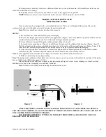
OPTIMUM CUTTING POSITION
BLADE ROTATION
NON-FERROUS HEAD
The optimum cutting position as shown above will put the center line of the blade 35 mm in front of the center line of
the material being cut.
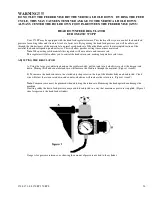
To maintain this cutting position, adjustment of the rear vise will be necessary.
This adjustment is made by loosening the rear vise and sliding it in the “T” slots forward or backward to reach the
optimum position.
Содержание Euromatic 370 S
Страница 9: ...370 S 370 S L 370 PP 370 PP L 9...
Страница 10: ...370 S 370 S L 370 PP 370 PP L 10 Actual control panel layout may vari...
Страница 32: ...370 S 370 S L 370 PP 370 PP L 32...
Страница 33: ...370 S 370 S L 370 PP 370 PP L 33...
Страница 38: ...ALIMENTAZIONE 230V 60Hz 230V 60Hz POWER SUPPLY POWER SUPPLY...
Страница 39: ...HL4 ILLUMINAZIONE LAMA POWER SUPPLY...
Страница 40: ...LAMPEGGIATORE LAMA IN MOTO 24VAC MORSA 24VAC EMERGENCIES...
Страница 41: ...DISCESA TESTA EV DISCESA TESTA START MEMORIA PULSANTE CICLO SB4 START CICLO ELECTROMECHANICALCIRCUIT...
Страница 44: ...9 11 2 4 5 10 3 6 7 8 1 CH1 LC4HR424ACJ KA5 RITORNO CARRO COUNTER...
Страница 45: ...TERMINAL...
Страница 49: ...10 2 2019 Euromatic 370 2 Head Cylinder Unit Ref 005...
Страница 51: ...10 2 2019 Euromatic 370 4 Bedplate Unit Ref 008...
Страница 53: ...10 2 2019 Euromatic 370 6 Head Unit Ref 002...
Страница 55: ...10 2 2019 Euromatic 370 8 Vise Unit Ref 004...
Страница 57: ...10 2 2019 Euromatic 370 10 Group Feeder P R...
Страница 59: ...10 2 2019 Euromatic 370 12 Group Alimentador P P Ref 014b Alimentador Ref 014b...


