370 S 370 S L 370 PP 370 PP L
29
HEAD CHANGE INSTRUCTIONS
(Initial set-up and adjustments)
If you have purchased the optional ferrous or non-ferrous cutting head for your machine, there may be a few
modifications needed for your machine. These modifications should be needed only once, during your initial set up.
GUARD MODIFICATION
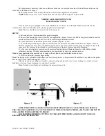
If your machine was purchased as a ferrous machine, your Plexiglas guard will need to be relocated. You will need to
unbolt the guard from its mounting, and shift the guard over to the right approx 2”. New holes (in hood brackets) will need to
be drilled to fasten this in its new position. The reason for this modification is due to the fact, the mounting plate and spindle
cap extends out from the head farther than ferrous head.
If you are installing a ferrous head onto a non-ferrous machine, this is modification may not be necessary. If it does
require moving the guard, complete the steps above only to the left.
INSTALLATION TIPS
A. Remove blade from cutting head before removal
B. Always mark the gib blocks when removed from head, to indicate where they came from.
Example:
Left rear, right rear, side.
Note: Always place these gib blocks in safe place to prevent damage to the gib blocks.
C. If changing heads will be done frequently, quick disconnects for the electrical may be installed. Each time the head
is to be changed, the motor must be unwired and then rewired when the other head is installed. To eliminate time and the need
for an electrician to complete this task, a short length of cord with a quick disconnect plug may be wired to each motor. A cord
from the machine will have a mating plug attached to it.
When ever a head is changed a simple twist of the plug and the motor is disconnected.
Note: If this system is used, make sure the plugs on the heads are wired for proper rotation. Clockwise for the non-
ferrous and counter clockwise for the ferrous head.
D: Always store the unused head upright and in a safe location.
HEAD REMOVAL
WARNING!!!!!
THE POWER AND AIR MUST BE LOCKED OUT BEFORE PERFORMING THIS
PROCEDURE.
Step 1:
Guard removal (Power must be off, and locked out)
A. Open the Plexiglas hood and safely hold it open. Having a helper or using a hoist to hold the hood open, remove the
clips holding the gas shocks to the hood. Lower the hood.
B. Lock the head in place (approx. half way down the column) using the upper and lower limit cams. Bring these cams
to a setting where the upper and lower limits both are being activated at the same time. This will hold the head while you
disconnect the air line.
C. Remove any tubing, wires, etc. Remove the way oilier tubing from head fittings, and anything that runs over the top
of the hoods brackets. Remove hood limit switch if applicable.
D. Remove the mounting bolts and remove the hood from the machine. Set it in a safe location.
WARNING!!!!!
THE POWER AND AIR MUST BE LOCKED OUT BEFORE PERFORMING THIS
PROCEDURE.
Step 2:
Replacing the gib plates. (Figure A on page 32)
A. Disconnect the wiring from the motor. (If quick release plug is used, disconnect it now) (ref. 1) B. Remove the rear
column cover plate, from the column casting. Place the six screws out of the way. (Two different covers are used for ferrous
and non-ferrous. The plate furnished on the machine will work for either head, unless you choose to connect a chip collection
Содержание Euromatic 370 S
Страница 9: ...370 S 370 S L 370 PP 370 PP L 9...
Страница 10: ...370 S 370 S L 370 PP 370 PP L 10 Actual control panel layout may vari...
Страница 32: ...370 S 370 S L 370 PP 370 PP L 32...
Страница 33: ...370 S 370 S L 370 PP 370 PP L 33...
Страница 38: ...ALIMENTAZIONE 230V 60Hz 230V 60Hz POWER SUPPLY POWER SUPPLY...
Страница 39: ...HL4 ILLUMINAZIONE LAMA POWER SUPPLY...
Страница 40: ...LAMPEGGIATORE LAMA IN MOTO 24VAC MORSA 24VAC EMERGENCIES...
Страница 41: ...DISCESA TESTA EV DISCESA TESTA START MEMORIA PULSANTE CICLO SB4 START CICLO ELECTROMECHANICALCIRCUIT...
Страница 44: ...9 11 2 4 5 10 3 6 7 8 1 CH1 LC4HR424ACJ KA5 RITORNO CARRO COUNTER...
Страница 45: ...TERMINAL...
Страница 49: ...10 2 2019 Euromatic 370 2 Head Cylinder Unit Ref 005...
Страница 51: ...10 2 2019 Euromatic 370 4 Bedplate Unit Ref 008...
Страница 53: ...10 2 2019 Euromatic 370 6 Head Unit Ref 002...
Страница 55: ...10 2 2019 Euromatic 370 8 Vise Unit Ref 004...
Страница 57: ...10 2 2019 Euromatic 370 10 Group Feeder P R...
Страница 59: ...10 2 2019 Euromatic 370 12 Group Alimentador P P Ref 014b Alimentador Ref 014b...


