370 S 370 S L 370 PP 370 PP L
19
This adjustment is necessary when ever a different blade size is used on the machine. With a different blade size the
center line of the blade will change.
By adjusting this rear vise you may also achieve a more or less aggressive cut position.
NOTE
: When ever the rear vise is moved the feeder vise must also be adjusted, on the 370 PP
.
VERTICAL HOLD DOWN VISE
EUROMATIC 370 PP
Your machine may be equipped with a vertical hold down vise. This vise will help hold the material flat on the
machines bed, and assist in bundle cutting, by keeping the material grouped.
Note:
This vise should never be used with out the main vise.
SET-UP:
A: Set material vises (feed and main) for proper clamping.
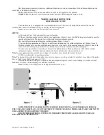
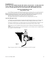
B: Choose the clamping foot most suited for your application. (Figure 1 items A & B)The long foot should be used for
smaller or flat material. The shorter feet will be used for larger diameter material.
This foot will screw on and off the piston of the cylinder. (Figure 1 item C)
C: Loosen the large mounting nut (figure 1 item D) from the bottom of the cylinder slide bracket. (Figure 1 item F)
With the cylinder nut loose, move the hold down foot over to the center of the material being cut. (Figure 2 item 4) In
some cases this foot may be positioned over a different area of the part for more control in clamping.
D: After foot and cylinder is centered over the material, tighten this nut. Hand tight usually will hold the cylinder
sufficiently in place. With this adjustment done, the foot should be above the material to be cut.
Note
: In some applications the material size or shape will not allow the vertical hold down to be used.
E: With vise adjusted, you may begin cutting.
Note
: The design of this cylinder will not allow over exertion of pressure to the part and will not affect the cylinder if the piston
does not fully stroke (Full stroke approx. 1 1/4”).
Other items shown are in Figure 1 item E is the electrical panel, figure 2 item 1 is rear feeding vise, item 2 vertical
hold down vise item 3 main clamping vise and item 4 material.
Note
: Vertical vise will only activate during the automatic run cycle!
NOTE: THE VERTICAL HOLD DOWN VISE MUST REMOVED TO ACCESS THE BLADE. REMOVE
THE VISE AND CAREFULLY LAY OUT OF THE WAY WHILE CHANGING THE BLADE. TAKE CARE NOT TO
DAMAGE THE TUBING OR THE CYLINDER!
FOR EXTREME MITERING CUTTING TO THE LEFT, THE VERTICAL HOLD DOWN VISE AND
BRACKET MUST BE REMOVED.
Содержание Euromatic 370 S
Страница 9: ...370 S 370 S L 370 PP 370 PP L 9...
Страница 10: ...370 S 370 S L 370 PP 370 PP L 10 Actual control panel layout may vari...
Страница 32: ...370 S 370 S L 370 PP 370 PP L 32...
Страница 33: ...370 S 370 S L 370 PP 370 PP L 33...
Страница 38: ...ALIMENTAZIONE 230V 60Hz 230V 60Hz POWER SUPPLY POWER SUPPLY...
Страница 39: ...HL4 ILLUMINAZIONE LAMA POWER SUPPLY...
Страница 40: ...LAMPEGGIATORE LAMA IN MOTO 24VAC MORSA 24VAC EMERGENCIES...
Страница 41: ...DISCESA TESTA EV DISCESA TESTA START MEMORIA PULSANTE CICLO SB4 START CICLO ELECTROMECHANICALCIRCUIT...
Страница 44: ...9 11 2 4 5 10 3 6 7 8 1 CH1 LC4HR424ACJ KA5 RITORNO CARRO COUNTER...
Страница 45: ...TERMINAL...
Страница 49: ...10 2 2019 Euromatic 370 2 Head Cylinder Unit Ref 005...
Страница 51: ...10 2 2019 Euromatic 370 4 Bedplate Unit Ref 008...
Страница 53: ...10 2 2019 Euromatic 370 6 Head Unit Ref 002...
Страница 55: ...10 2 2019 Euromatic 370 8 Vise Unit Ref 004...
Страница 57: ...10 2 2019 Euromatic 370 10 Group Feeder P R...
Страница 59: ...10 2 2019 Euromatic 370 12 Group Alimentador P P Ref 014b Alimentador Ref 014b...


