16
|
Special requirements for R32 units
Installer and user reference guide
77
RYMA5+RXYA8~20A7Y1B
VRV 5 heat pump
4P749918-1 – 2023.12
16.4.4 Shut-off valves
In case shut-off valves are required as a safety measure, SV unit which has shut-off
valves needs to be installed to reduce the amount of refrigerant leakage in to the
room where the indoor unit is installed.
For installation of the SV unit, refer to the installation and operation manual
delivered with the SV unit.
The maximum amount of charge limit and so the maximum capacity class of indoor
unit which is allowed to install in the room is determined as below.
About the charge limit
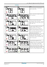
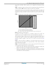
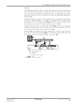
The charge limit must be determined separately for
each
SV
unit branch pipe port
.
This is possible because of the shut-off valves in the SV unit. The maximum amount
of refrigerant that can escape in case of a leak is determined by the piping length
and indoor heat exchanger size. This is directly linked to the downstream indoor
unit capacity of this piping section.
In case a leak is detected in an indoor unit, the shut-off valves in the SV unit of the
respective port will close. The piping section with the leak is now shut off from the
rest of the system and the amount of refrigerant that can leak is significantly
reduced.
Note:
When two branch pipe ports are combined in order to form a single branch
pipe port (e.g. FXMA200/250), they must be considered as a single branch pipe
port.
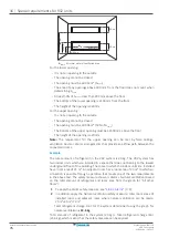
To determine the charge limit
Step 1
– In order to derive the total refrigerant charge limit in the system,
determine the area
▪
of the rooms where an indoor unit is installed,
▪
AND of the area of the rooms served by a ducted indoor unit installed in a
different room.
The room area can be determined by projecting the walls, doors and partitions to
the floor and calculate the enclosed area. The area of the smallest room being
served by a port of the SV unit is used in the next step to determine the maximum
allowable indoor capacity that can be connected to that port.
Spaces connected by only false ceilings, ductwork, or similar connections shall NOT
be considered a single space.
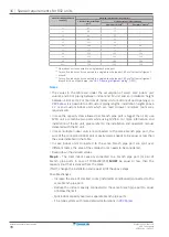
Step 2
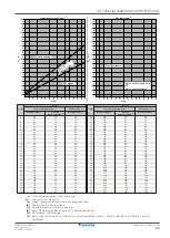
– Use the table below to determine the maximum total indoor unit capacity
(sum of all connected indoor units) that is allowed for a single SV unit branch pipe
port. In case a ducted indoor unit is serving a different room than where it is
installed, the restrictions of the room area apply to both the indoor installation
room as the conditioned room separately. Supply and return air shall be directly
ducted to that room.
Area of installed/conditioned
room [m²]
Maximum total indoor unit capacity class
1 indoor unit per branch pipe
port
(a)
2~5 indoor units per branch pipe port
40 m after 1
st
branch
(b)
90 m after 1
st
branch
(c)
<5
—
—
—
5
10
—
—
6
25
—
—
7
32
—
—
8
40
—
—
9
71
—
—
10
80
—
—
Содержание VRV 5 RXYA8A7Y1B
Страница 197: ......
Страница 198: ......
Страница 199: ......
Страница 200: ...4P749918 1 2023 12 Copyright 2023 Daikin Verantwortung f r Energie und Umwelt...


