


Field settings
ESIE04-01
4–18
Part 4 – Commissioning and Test Run
3
1
4
5
2.9
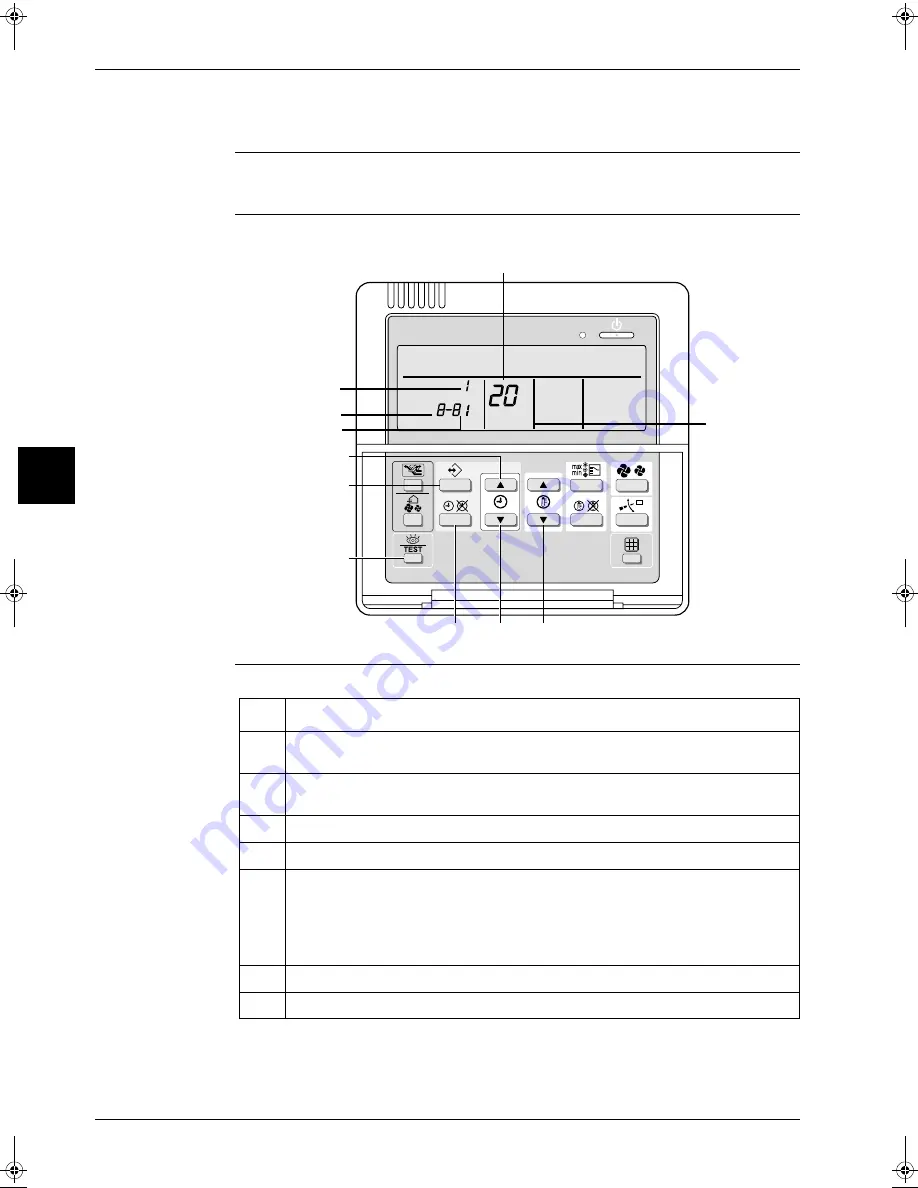
Setting the Centralized Group No.
When?
If you want to carry out centralized control with a central remote controller and a unified ON/OFF
controller, you have to set the group No. for each group with the remote controller.
Wired remote
controller
The illustration below shows the wired remote controller.
Setting
To set the “Centralized group No.”, proceed as follows:
SETTING
UNIT No.
GROUP
3
1
4
5
6
2
7
Unit N°
First Code N°
Second Code N°
Mode N°
Field set mode
Step
Action
1
Switch ON the power supply of the central remote controller, the unified ON/OFF control-
ler and the indoor unit(s).
2
Hold down the INSPECTION/TEST button for at least 4 s during normal mode to enter
the “Field setting mode”.
3
Press the TEMPERATURE CONTROL button until “Mode No.” “
00
” appears.
4
Press the INSPECTION/TEST button to inspect the group No. display.
5
Set the “Group No.” for each group by pressing the PROGRAMMING TIME button.
The “Group No.” rises in the order of 1—00, 1—01, ..., 1—15, 2—00, ..., 2—15, 3—00,
etc.
The unified ON/OFF controller however displays only the range of group numbers
selected by the switch for setting each address.
6
Press the CONFIRMATION button to enter the selected group No.
7
Press the INSPECTION/TEST button to return to normal mode.
RZQ - Final.book Page 18 Wednesday, September 8, 2004 8:40 AM
Содержание RZQ71~125B7V3B
Страница 1: ...Service Manual ESIE04 01 RZQ71 125B7V3B Sky Air Inverter R 410A B series ...
Страница 2: ......
Страница 24: ...ESIE04 01 1 2 Part 1 System Outline 3 1 1 5 ...
Страница 32: ...General Outline Outdoor Units ESIE04 01 1 10 Part 1 System Outline 3 1 1 4 5 ...
Страница 64: ...General Outline Indoor Units ESIE04 01 1 42 Part 1 System Outline 3 1 1 4 5 ...
Страница 76: ...Specifications ESIE04 01 1 54 Part 1 System Outline 3 1 1 4 5 ...
Страница 92: ...Functional Diagrams ESIE04 01 1 70 Part 1 System Outline 3 1 1 4 5 ...
Страница 94: ...ESIE04 01 1 72 Part 1 System Outline ...
Страница 122: ...Wiring Diagrams ESIE04 01 1 100 Part 1 System Outline 3 1 1 4 5 ...
Страница 140: ...ESIE04 01 2 2 Part 2 Functional Description 3 1 2 5 ...
Страница 162: ...General Functionality ESIE04 01 2 24 Part 2 Functional Description 3 1 2 4 5 ...
Страница 200: ...Outdoor Unit Functional Concept ESIE04 01 2 62 Part 2 Functional Description 3 1 2 4 5 ...
Страница 202: ...ESIE04 01 3 2 Part 3 Troubleshooting 3 1 3 5 ...
Страница 288: ...Error Codes Outdoor Units ESIE04 01 3 88 Part 3 Troubleshooting 3 1 3 4 5 ...
Страница 312: ...Additional Checks for Troubleshooting ESIE04 01 3 112 Part 3 Troubleshooting 3 1 3 4 5 ...
Страница 314: ...ESIE04 01 4 2 Part 4 Commissioning and Test Run 3 1 4 5 ...
Страница 356: ...ESIE04 01 5 2 Part 5 Disassembly and Maintenance 3 1 5 ...
Страница 370: ...Disassembly and Maintenance Outdoor Units ESIE04 01 5 16 Part 5 Disassembly and Maintenance 3 1 5 5 ...
Страница 476: ...Disassembly and Maintenance Indoor Units ESIE04 01 5 122 Part 5 Disassembly and Maintenance 3 1 5 5 ...
Страница 484: ...ESIE04 01 viii Index 3 1 4 5 ...