background image

įĂĀĂĀƫ5!.ƫ+3!.ƫ5/0!)/ƫĨĩČƫ *ċƫ((ƫ.%#$0/ƫ.!/!.2! ċƫ((ƫ+0$!.ƫ0. !).'/ƫ.!ƫ0$!ƫ,.+,!.05ƫ+"ƫ0$!%.ƫ.!/,!0%2!ƫ+3*!./ċƫ

26

USING THE UPS SYSTEM CONT.

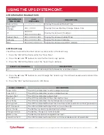
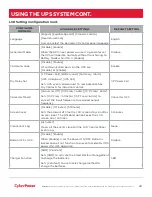
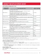
LCD Setting Configuration Cont.

8. Press the “ENTER” button to select the parameter you want to change.

9. You may be prompted to save the selection, if so press the “ENTER” button to save the setting. Some

options are saved and started automatically. (See the following table for additional details.)

10. Press the “ESC” button to cancel or return to the previous LCD menu.

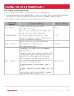
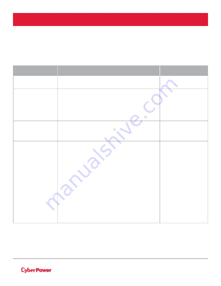
CONFIGURE 

SUBMENU

AVAILABLE SETTINGS

DEFAULT SETTING

Output Voltage

= [200V] [208V] [220V] [230V] [240V]

Sets UPS output voltage

208V

Sync Freq Window

Range= [+/- 1%] [+/- 2%] [+/- 3%] [+/- 4%] [+/- 5%]

[+/- 6%] [+/- 7%] [+/- 8%] [+/- 9%] [+/-10%]

Sets output synchronization frequency range

If input line frequency is outside this range, the UPS 
will lock in at the nominal frequency

+/- 5%

Bypass V Window

Range= [+10%/-10%] [+10%/-15%] [+10%/-20%]

[+15%/-10%] [+15%/-15%] [+15%/-20%]

Sets Bypass Voltage range

+10%/-15%

Bypass Condition

[Check Freq/Volt] [Check Volt Only] [No Bypass]

Bypass Condition :

The default setting [Check Freq/Volt] means the UPS 
will check the the following specifications (1) and (2) 
when UPS has fault and needs transfer to Bypass.

The setting [Check Volt Only] means the UPS will 
check the the following specification (1) when UPS has 
fault and needs transfer to Bypass.

(1) Bypass voltage is inside the range of "Bypass V
Window".

(2) Bypass frequency is inside the range of "Sync Freq
Range".

The setting [No Bypass] means the UPS is forbidden 
to transfer to Bypass when UPS has fault.

Check Freq/Volt

Содержание OL10KRTHW

Страница 1: ...nual and follow the instructions for installation and operation 20ĂĀ Cyber Power Systems Inc All rights reserve K01 Ā000ĈĆć 0ā INSTALLATION AND OPERATION MANUAL SMART APP ONLINE UPS SYSTEM OL6KRTMB OL8KRTMB OL10KRTMB OL6KRTHW OL8KRTHW OL10KRTHW ...

Страница 2: ...artApp Online 6 10kVA UPS models that are covered in this manual are intended for installation in an environment within 32 F to 104 F 0 C to 40 C free of conductive contaminants SPECIAL SYMBOLS Warning High voltage Risk of Electric Shock Caution Important Instructions must always be followed Do Not Discard the UPS or UPS batteries in trash The batteries contain lead acid For more information conta...

Страница 3: ...equipment and cause fire hazards Make sure everything is turned off and disconnected completely before conducting any maintenance repairs or shipment DO NOT INSTALL THE UPS WHERE IT WOULD BE EXPOSED TO DIRECT SUNLIGHT OR NEAR A STRONG HEAT SOURCE DO NOT BLOCK OFF VENTILATION OPENINGS AROUND THE HOUSING DO NOT CONNECT DOMESTIC APPLIANCES SUCH AS HAIR DRYERS TO UPS OUTPUT SOCKETS SERVICING OF BATTER...

Страница 4: ... the unit even when the AC input power is disconnected The UPS should be placed near the connected equipment and easily accessible Non Isolated Battery Supply Risk of electric shock battery circuit is not isolated from AC power source hazardous voltage may exist between battery terminals and ground Test before touching All UPS models covered in this document are permanently connected equipment and...

Страница 5: ...ċƫ ƫ 0 ƫ0 ƫ ƫ0 ƫ 05ƫ ƫ0 ƫ 0 2 ƫ 3 ċƫ BATTERY Do not dispose of batteries in fire as the battery may explode Do not open or mutilate the battery released electrolyte is harmful to the skin and eyes SAFETY INSTRUCTIONS CONT PRODUCT SAFETY CONT ...

Страница 6: ...r Installation 11 MAINTENANCE BYPASS MODULE INSTALLATION 12 Electrical Installation 13 Input Output Configuration 14 Backfeed Protection Operation 14 Without Backfeed Protection Configuration 15 With Backfeed Protection Configuration 15 EXTENDED BATTERY MODULE INSTALL 16 Rear Panel Description 16 Connection With Power Module 16 OPTIONAL LCD CONTROL PANEL INSTALLATION 19 Remote Control 19 Wall moun...

Страница 7: ...managing the UPS Smart App Online UPS systems come with a three year warranty and a 300 000 Connected Equipment Guarantee UPS EXTENDED BATTERY MODULES Extended Battery Modules EBMs from CyberPower increase battery runtimes during power outages Each rack tower convertible EBM uses 3U of rack space depending upon the model and can be installed in a tower form factor to match the UPS installation The...

Страница 8: ...afety shoes and use hydraulic equipment lift if one is available At least two people are required for all handling operations including unpacking lifting and installation in rack system Do not use the lifting straps to carry the unit around they are provided for manually unpacking the unit from the carton only USE LIFTING STRAPS TO REMOVE UNIT FROM THE BOX Information advice help ...

Страница 9: ...RTHW and OL10KRTHW models 4 Rackmount left rail 2 5 Rackmount right rail 2 6 Left hanging bracket 2 7 Right hanging bracket 2 8 Phone line 1 9 USB communication cable 1 10 Serial Interface Cable RS 232 1 ITEM CONTENT QTY 11 NEMA L6 30R to IEC 320 C13 power cord 1 12 Quick Start Guide 1 13 0 0 ƫ ƫ 0 ƫ 1 1 14 Registration warranty card 1 15 PowerPanel Management software download card 1 16 Rackmount...

Страница 10: ...werPanel Business Edition Agent software on the PC Server connected with the USB cable 6 Serial Port Serial port provides communication between the UPS and the computer The UPS can control the computer s shutdown during a power outage through the connection while the computer can monitor the UPS and alter its various programmable parameters 7 Surge Protected Communication Ports RJ 45 RJ 11 These p...

Страница 11: ...UPS power off from a remote location 12 Extended Battery Module Connector Connection for additional CyberPower Extended Battery Modules EBM 13 Input Output Connectors Use these connectors to attach the Maintenance Bypass Module to the power module MAINTENANCE BYPASS MODULE OL6KMBM OL6KMBMHW OL8K10KMBM OL8K10KMBMHW 3 1 2 4 8 9 5 5 3 1 2 4 6 7 4 2 1 3 8 9 6 7 1 2 4 3 ...

Страница 12: ...e these connectors to attach the Maintenance Bypass Module to the power module 7 Connector Cover Provides safety protection when removing the Maintenance Bypass Module 8 Output Circuit Breaker Provides output overload and fault protection 9 Battery Backup Surge Protected Outlets Provides battery backup and surge protection They ensure power is provided to connected equipment over a period of time ...

Страница 13: ...he outlets only when the UPS is off and unplugged DO NOT plug a laser printer copier space heater vacuum paper shredder or other large electrical device into the UPS The power demands of these devices will overload and possibly damage the unit 4 To protect a fax machine telephone modem line or network cable connect the telephone or network cable from the wall jack outlet to the jack marked IN on t...

Страница 14: ...n monitor the UPS and alter various programmable parameters Note Only one communication port can be used at a time The port not in use will automatically become disabled or the serial port will be disabled if both ports are attached 10 EPO Emergency Power Off Port EPO ports allow administrators the capability to connect the UPS unit to customer supplied EPO switches These installations give operat...

Страница 15: ...wo rackmount ears to the UPS using the provided flat head screws M5X7L 8pcs and tighten two hanging brackets with the pan head screws M5X6L 6pcs Step 3 Rackmount rail Installation The rails adjust to mount in 19 in 48 cm racks from 20 5 in to 36 in 52 cm to 91 5 cm deep Select the proper holes in the rack for positioning the UPS in the rack The UPS uses 3 rack units rack holes positions 1 through ...

Страница 16: ...5 position 7 Once completed perform the same steps for the Battery module Remove the internal battery trays from the Battery module before installing it See Battery Replacement section The Battery module must be installed below the Power module Place the internal battery trays back into the Battery module after installation See Battery Replacement section NOTE To slide the UPS out from the rack Th...

Страница 17: ...e power module and extended battery module with the flat head screws M5X7 4pcs Insert dust covers into the screw holes that are not being used Optionally use the rack mount ears as tower stands Screw them onto the power module and extended battery module with pan head screws M5X6L 4pcs for adding stability Step 3 Rotate the Multifunction LCD Control Panel Unscrew the upper panel of the UPS Separat...

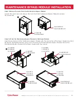
Страница 18: ...ule to the Power Module Align the connectors of the Maintenance Bypass Module with the connectors of the Power module to attach the device and tighten the two screws to fix the cover on the Maintenance Bypass Module Secure the Maintenance Bypass Module to the Power module with four screws OL6KMBM OL8K10KMBM OL6KMBMHW OL8K10KMBMHW OL6KPMB OL8KPMB OL10KPMB OL6KPMB OL8KPMB OL10KPMB OL6KMBM OL8K10KMBM...

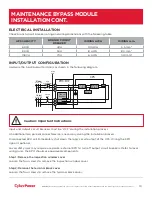
Страница 19: ...O signal is optional Local safety rules may require a separate external EPO to turn off output circuit breakers Refer to local wiring rules the EPO should use approved components Step 1 Remove the inspection window cover Loosen the four screws to remove the inspection window cover Step 2 Remove the terminal block cover Loosen the four screws to remove the terminal block cover UPS CAPACITY BRANCH C...

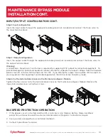
Страница 20: ... output cable through the appropriate cable gland not included and connect the three wires to the output terminal block Step 5 Fix the terminal block cover on the Maintenance Bypass Module Tighten the four screws to fix the terminal block cover on the Maintenance Bypass Module Replace the inspection window cover using four screws 4 5 MAINTENANCE BYPASS MODULE INSTALLATION CONT Warning A CyberPower...

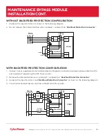
Страница 21: ...side the UPS and capable of supporting the UPS input current 2 Remove the interconnection wires Jumper1 Jumper2 on Backfeed Protection Connector 3 Hardwire the input terminals and Backfeed Protection Connector as shown in the following diagram 4 The external isolation device must be installed in the Mains path UPS L1 L2 PSDR AC L1 AC L2 IP L1 IP L2 Backfeed 1 2 4 5 3 L1 L2 I P EMI L1 L2 L1 L2 PE M...

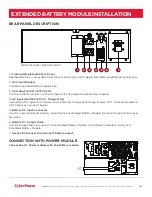
Страница 22: ...ce for Fast Charge Technology feature NOT to be connected to UPS output as source of power 5 Battery DC Input Connector Use this input connector to daisy chain the next Extended Battery Module Remove the connector cover for access 6 Battery DC Output Cable Use this output cable to connect the Extended Battery Module to the Power module or to the next Extended Battery Module 7 Use the DC breaker to...

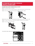
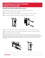
Страница 23: ...tery cable retention bracket and tighten the two screws to fix battery cable Step 5 Use a power cord to plug AC input inlet of the battery module into a wall receptacle Step 6 Turn on the DC breaker of the EBM Connection 2 Power module with multiple battery modules 1 2 OFF 4 6 ON 287387 KDUJH 2QO 1387 9a 86 3 8 172 5 37 5 287387 287 1 86 56 86 9a 1387 KDUJH 2QO 287 287 3527 7 21 211 725 77 5 1387 ...

Страница 24: ... tighten the two screws to fix battery cable Step 6 Use a power cord to plug AC input inlet of the 2nd EBM into AC output outlet of the 1st EBM Step 7 Turn on the DC breaker of the 2nd EBM Step 8 Set the EBM number to the respective setting to match the number of installed units To do this via the LCD control panel go to the Configuration Menu then scroll to EBM Number setting select the appropria...

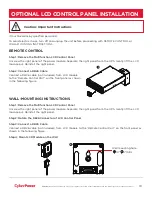
Страница 25: ...ep 2 Connect a DB26 Cable Connect a DB26 cable not included from LCD module to the Remote Control Port on the front panel as shown in the following figure WALL MOUNTING INSTRUCTIONS Step 1 Remove the Multifunction LCD Control Panel Unscrew the right panel of the power module Separate the right panel from the UPS Gently lift the LCD module out Reinstall the right panel Step 2 Rotate the DB26 Connec...

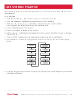
Страница 26: ...crew 4 Set the EBM DC breaker to ON position 5 Set the UPS input circuit breaker to ON position 6 Set the upstream circuit breaker not provided to the ON position The UPS LCD shows CyberPower and fans turn on 7 Press the ON OFF button on the UPS front panel for at least 3 seconds to start the UPS 8 UPS will perform a brief self test lasting about 15 seconds The LCD will show result in the sequence...

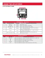
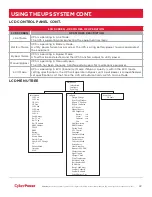
Страница 27: ... in Bypass Mode Manual Bypass or ECO Economy Mode 5 FAULT Red UPS has an internal fault See Trouble Shooting for additional information 6 REPLACE BATTERY Red Battery will soon need to be replaced due to insufficient runtime 1 2 7 3 8 4 9 5 10 6 11 BUTTON OPERATION ITEM BUTTON UPS MODES DESCRIPTION 7 ON OFF Press this button for at least 3 seconds to turn on or turn off UPS 8 S Press this button to...

Страница 28: ...Bypass quality is within the ECO mode setting specifications the UPS will operate in Bypass until input power is disqualified per set specifications At that time the UPS will automatically switch to Line Mode O P Volt O P Freq I P Volt I P Freq O P Load O P Amp O P Watt O P VA Load Energy BAT Volt BAT Cap BAT Runtime EBM Number TEMP SBM Rating MCU Ver Model Name Date Time Next BATT Change IP Subne...

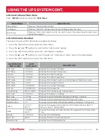
Страница 29: ...ENU ITEMS DATA DISPLAYED DESCRIPTION O P Volt XXX XV Displays the Output Voltage O P Freq XX XHz Displays the Output Frequency I P Volt XXX XV Displays the Input Voltage I P Freq XX XHz Displays the Input Frequency O P Load XXX Displays the Output Load as a Percentage of Maximum Load O P Amp X XA Displays the Output Current O P Watt XXXXXW Displays the Output Wattage O P VA XXXXXVA Displays the Ou...

Страница 30: ...ubmenu 4 Press the S and T buttons to scroll through the Event Log The UPS will record events listed in the table below 5 Press the ESC button to return to UPS Status EVENT LOG SUBMENU DESCRIPTION X Event date and time followed by event description EVENT CONTENT DESCRIPTION High O P V The UPS has detected Inverter voltage too High Low O P V The UPS has detected Inverter voltage too Low Output shor...

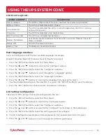
Страница 31: ...çais French Deutsch German 1 Press the ENTER button to enter the Main Menu 2 Press the and buttons to scroll to the Configure option 3 Press the ENTER button to select the Configure submenu 4 Press the and buttons to scroll through the Language options 5 Press the ENTER button to select the Language submenu 6 Press the and buttons to scroll to the language that you want to select You may be prompt...

Страница 32: ... 7 8 9 10 Sets output synchronization frequency range If input line frequency is outside this range the UPS will lock in at the nominal frequency 5 Bypass V Window Range 10 10 10 15 10 20 15 10 15 15 15 20 Sets Bypass Voltage range 10 15 Bypass Condition Check Freq Volt Check Volt Only No Bypass Bypass Condition The default setting Check Freq Volt means the UPS will check the the following specifi...

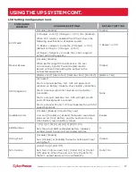
Страница 33: ...t Fan Test Battery Test Activate Starts a manual battery test UPS will operate 10 seconds on Battery mode to check battery condition Starts a manual Alarm test buzzer will sound for 5 seconds Starts a manual Indicator test UPS will light all LED and LCD background 5 seconds Starts a manual Fan test UPS will operate fan with full speed 5 seconds None Audible Alarms Disable Enable Only Battery Low U...

Страница 34: ...eal potential free Dry Contacts for industrial control I P Power Fail Converter Mode3 Converter Off O P Freq 50Hz O P Freq 60Hz Sets O P Freq 50Hz or O P Freq 60Hz to convert the input frequency to required output frequency Converter OFF Screen Saver Disable 1 Minutes 5 Minutes Sets the amount of time the LCD screen stays on after no user input The Disable option keeps the LCD screen on at all tim...

Страница 35: ...abled the Smart Battery Management SBM carries out battery tests when certain operating conditions are met Disable EPO ROO Sets EPO Emergency Power Off to shutdown the UPS remotely when the contact is open Sets ROO Remote On Off to turn On the UPS remotely when the contact is close and turn Off the UPS remotely when the contact is open The On Off power button on front panel will be disable when se...

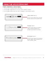
Страница 36: ... THE UPS SYSTEM CONT LOAD and BAT Capacity The LCD screen displays the Load and Battery capacity with a graphical icon Charging Capacity The LCD screen displays the battery capacity during charging with a graphical icon while on Line Mode Discharging Capacity The LCD screen displays the remaining battery capacity with a graphical icon while on Battery Mode įĂĀĂĀƫ 5 ƫ 3 ƫ 5 0 ƫĨ ĩČƫ ċƫ ƫ 0 ƫ 2 ċƫ ƫ...

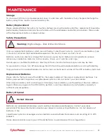
Страница 37: ... skin eyes and may be toxic To avoid electric shock turn off and unplug the UPS from the wall receptacle before servicing the battery Only use tools with insulated handles Do not lay tools or metal parts on top of the UPS or battery terminals Replacement Batteries Please refer to the front side of the EBM for the model number of the correct replacement batteries For battery procurement log onto ww...

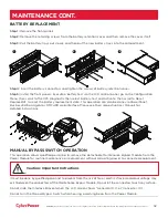
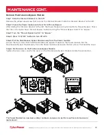
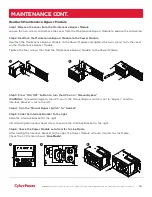
Страница 38: ...ment date This operation can also be done via PowerPanel Business Edition Agent or RMCARD web interface Please see their respective User Manuals for detailed instructions MANUAL BYPASS SWITCH OPERATION This operation allows qualified personnel to remove the detachable Maintenance Bypass Module from the Power Module for routine maintenance or replacement without disrupting power to connected equipm...

Страница 39: ...al Bypass Switch to Bypass Step 3 Turn the Manual Bypass Switch to Bypass Step 4 Press ON OFF button to turn off UPS Step 5 Pull the Maintenance Bypass Module away from the Power module Loosen the four screws that hold the Maintenance Bypass Module to the Power module Pull the Maintenance Bypass Module away from the Power module and loosen the two screws that hold the cover Step 6 Fix the cover on...

Страница 40: ... Tighten the four screws that hold the Maintenance Bypass Module to the Power Module Step 3 Press ON OFF button to turn the UPS on in Manual Bypass WARNING to avoid damage to the UPS verify the Manual Bypass switch is set to Bypass and the Interlock Bracket is set to the left Step 4 Turn the Manual Bypass Switch to Normal Step 5 Slide the Interlock Bracket to the right Slide the Interlock Bracket ...

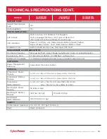
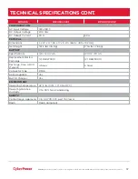
Страница 41: ...g or Configurable Transfer Time Typical 0ms Rated Power Factor 1 Harmonic Distortion THD 3 at Linear Load 5 at Non linear Load Crest Factor 3 1 ECO Mode Bypass Voltage Range 10 15 Configurable Outlets for the Maintenance Bypass Module with Outlets 2 L6 20R 4 L6 30R 1 Hard Wire 3 wire Outlets for the Maintenance Bypass Module without Outlets 1 Hard Wire 3 wire PROTECTION Surge Protection IEC 61000 ...

Страница 42: ...lt MANAGEMENT COMMUNICATIONS On Device Features Start up Self Test Auto Charge Auto Restart Auto Overload Recovery Connectivity Ports 1 Serial Port RS232 1 USB Port 1 Relay Out SNMP HTTP Capable 1 Remote management card is pre installed in expansion slot SOFTWARE Power Management Software PowerPanel Business Edition PHYSICAL Dimensions Power Module L x W x H 26 x 17 05 x 5 2 in 66 x 43 3 x 13 2 cm...

Страница 43: ... 17 x 5 2in 660 x 433 x 132 mm Net Weight 167 2 lbs 76 Kg 171 6 lbs 78 Kg BATTERY Specifications 20 12 V 7 Ah 20 12 V 9 Ah Replacement Battery Cartridge 2 RB1270X10 2 RB1290X10 Recharge Time 0 90 Typical 4 hours 5 hours Connector Type PP45 Hot Swappable Yes Built in Charger Yes ENVIRONMENT Operating Temperature 32 F to 104 F 0 C to 40 C Operating Relative Humidity 0 to 90 Non Condensing SAFETY Con...

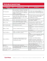
Страница 44: ...turns BAT Disconnected Missing battery power Check battery connector and battery breaker Battery Failure UPS has failed in Battery Test Check battery connector and battery breaker Contact technical support to replace the battery Replace Battery Battery will need to be replaced soon due to insufficient runtime Install new batteries execute battery test and reset the replace battery date Service Bat...

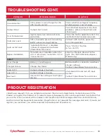
Страница 45: ...pass Forbidden when the LCD screen shows Generator On or Converter On Slide the Interlock Bracket to the right For the Maintenance Bypass Module only FAULT Over Charge Battery is overcharged Remove battery connector and check charger voltage Contact CyberPower for assistance Charger Failure Charger has failed High O P V Output voltage is too high Shut down UPS and turn off input breaker Contact Cy...

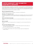
Страница 46: ...nty Cover This warranty covers defects in materials and workmanship in the Product under normal use and conditions It also covers equipment that was connected to the Product and damaged because of the failure of the Product What is the Period of Coverage This warranty covers the Product for three years and connected equipment for as long as you own the Product Who Is Covered This warranty only cov...

Страница 47: ...oduct You must prepay all shipping costs you are responsible for packaging and shipment and you must pay the cost of the repair estimate How Long Do I Have To Make A Claim All claims must be made within ten days of the occurrence What Will We Do To Correct Problems CyberPower will inspect and examine the Product If the Product is defective in material or workmanship CyberPower will repair or repla...

Страница 48: ...Product surge suppressor or power tap Any such installation voids the Limited Warranty 3 The Product and equipment connected to it must have been used properly in a suitable and proper environment and in conformance with any license instruction manual or warnings provided with the Product and the equipment connected to it 4 The Product must have been used at all times within the limitations on the...

Страница 49: ...ous environments requiring fail safe performance or for use in any circumstance in which the failure of the Product could lead directly to death personal injury or severe physical or property damage or that would affect operation or safety of any medical or life support device collectively High Risk Activities CyberPower expressly disclaims any express or implied warranty of fitness for High Risk ...

Страница 50: ...ate but CyberPower reserves the right to change or correct the contents and does not assume any responsibility for omissions or errors Need Additional Help Feel free to contact our Tech Support department with installation troubleshooting or general product questions CyberPower Technical Support Phone 1 877 297 6937 Email tech cpsww com Web www cyberpowersystems com Address 4241 12th Avenue E Suit...

Страница 51: ... 3 5 0 ċ For USA and Canada 4241 12th Ave East Suite 400 Shakopee MN 55379 Toll free 877 297 6937 For all other regions Please visit our website for local contact information Copyright 20ĂĀ Cyber Power Systems Inc All rights reserve ...

Отзывы: