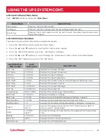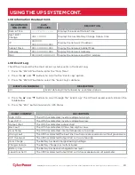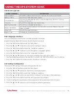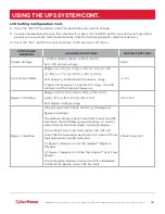
įĂĀĂĀƫ5!.ƫ+3!.ƫ5/0!)/ƫĨĩČƫ *ċƫ((ƫ.%#$0/ƫ.!/!.2! ċƫ((ƫ+0$!.ƫ0. !).'/ƫ.!ƫ0$!ƫ,.+,!.05ƫ+"ƫ0$!%.ƫ.!/,!0%2!ƫ+3*!./ċƫ
11
HARDWARE INSTALLATION CONT.
VERTICAL/TOWER INSTALLATION
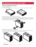
Step 1: Adhere rubber pads
Adhere the protective rubber pads on the bottom side of power module and extended battery module.
Step 2: Attach the base stands and attach the dust covers
Secure the tie bracket on top of the power module and extended battery module with the flat head screws
(M5X7*4pcs). Insert dust covers into the screw holes that are not being used. Optionally, use the rack mount
ears as tower stands. Screw them onto the power module and extended battery module with pan head
screws M5X6L*4pcs for adding stability.
Step 3: Rotate the Multifunction LCD Control Panel
Unscrew the upper panel of the UPS. Separate the upper panel from the UPS. Gently lift the LCD control
panel out. Rotate it to the tower orientation. Reinstall it for a tower configuration.
3
1
2


