įĂĀĂĀƫ5!.ƫ+3!.ƫ5/0!)/ƫĨĩČƫ *ċƫ((ƫ.%#$0/ƫ.!/!.2! ċƫ((ƫ+0$!.ƫ0. !).'/ƫ.!ƫ0$!ƫ,.+,!.05ƫ+"ƫ0$!%.ƫ.!/,!0%2!ƫ+3*!./ċƫ
34
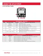
%$77(5<
)$8/7
%<3$66
21/,1(%$77(5<
5(3/$&(
21
(17(5
(6&
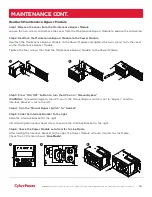
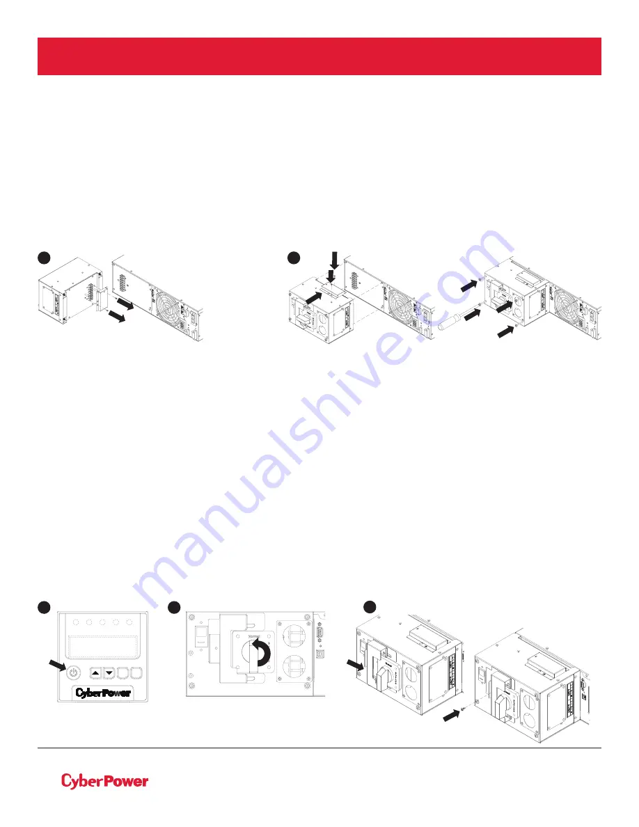
Reattach Maintenance Bypass Module
Step 1: Remove the cover from the Maintenance Bypass Module
Loosen the two screws and remove the cover from the Maintenance Bypass Module to expose the connectors.
Step 2: Reattach the Maintenance Bypass Module to the Power Module
Reattach the Maintenance Bypass Module to the Power Module and tighten the two screws to fix the cover
on the Maintenance Bypass Module.
Tighten the four screws that hold the Maintenance Bypass Module to the Power Module.
Step 3: Press “ON/OFF“ button to turn the UPS on in “Manual Bypass”
WARNING:
to avoid damage to the UPS, verify the Manual Bypass switch is set to “Bypass” and the
Interlock Bracket is set to the left.
Step 4: Turn the “Manual Bypass Switch“ to “Normal“
Step 5: Slide the Interlock Bracket to the right
Slide the Interlock Bracket to the right.
Install and tighten yellow head screw to secure the Interlock Bracket to the right.
Step 6: Check the Power Module auto transfer to Line Mode
After Sliding the Interlock Bracket to the right, the Power Module will auto transfer to Line Mode.
Check the LCD screen shows “
Line Mode
”.
MAINTENANCE CONT.
3
4
5
1
2

