įĂĀĂĀƫ5!.ƫ+3!.ƫ5/0!)/ƫĨĩČƫ *ċƫ((ƫ.%#$0/ƫ.!/!.2! ċƫ((ƫ+0$!.ƫ0. !).'/ƫ.!ƫ0$!ƫ,.+,!.05ƫ+"ƫ0$!%.ƫ.!/,!0%2!ƫ+3*!./ċƫ
18
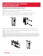
CONNECTION WITH POWER MODULE CONT.
Step 1:
Connect the 1st EBM to the Power module following the instructions above.
Step 2:
Turn off the DC breaker of the 2nd EBM.
Step 3:
Loosen the two screws to remove the battery cable retention bracket of the 1st EBM.
Step 4:
Use the output cable of the 2nd EBM to connect the 2nd EBM to the 1st EBM.
Step 5:
Rotate the battery cable retention bracket and tighten the two screws to fix battery cable.
Step 6:
Use a power cord to plug AC input inlet of the 2nd EBM into AC output outlet of the 1st EBM.
Step 7:
Turn on the DC breaker of the 2nd EBM.
Step 8:
Set the EBM number to the respective setting to match the number of installed units. To do this
via the LCD control panel, go to the Configuration Menu, then scroll to EBM Number setting, select the
appropriate number and Save the setting. This operation can also be done if there is an RMCARD installed
in the UPS, or via PowerPanel® Business Edition Agent. Please see their respective User’s Manuals for
instructions.
2
3
OFF
5
7
ON
EXTENDED BATTERY MODULE
INSTALLATION CONT.


