įĂĀĂĀƫ5!.ƫ+3!.ƫ5/0!)/ƫĨĩČƫ *ċƫ((ƫ.%#$0/ƫ.!/!.2! ċƫ((ƫ+0$!.ƫ0. !).'/ƫ.!ƫ0$!ƫ,.+,!.05ƫ+"ƫ0$!%.ƫ.!/,!0%2!ƫ+3*!./ċƫ
12
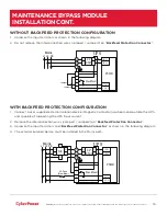
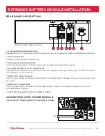
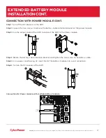
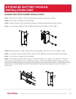
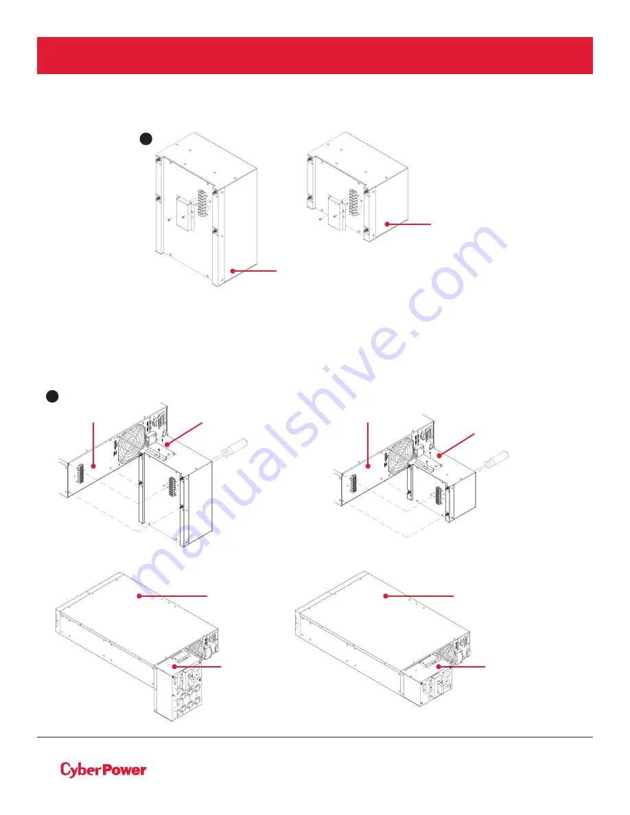
MAINTENANCE BYPASS MODULE INSTALLATION
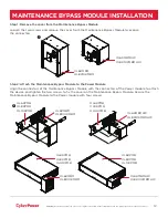
Step 1: Remove the cover from the Maintenance Bypass Module
Loosen the two screws and remove the cover from the Maintenance Bypass Module to expose
the connectors.
Step 2: Attach the Maintenance Bypass Module to the Power Module
Align the connectors of the Maintenance Bypass Module with the connectors of the Power module to attach
the device and tighten the two screws to fix the cover on the Maintenance Bypass Module. Secure the
Maintenance Bypass Module to the Power module with four screws.
OL6KMBM
OL8K10KMBM
OL6KMBMHW
OL8K10KMBMHW
OL6KPMB
OL8KPMB
OL10KPMB
OL6KPMB
OL8KPMB
OL10KPMB
OL6KMBM
OL8K10KMBM
OL6KMBMHW
OL8K10KMBMHW
OL6KPMB
OL8KPMB
OL10KPMB
OL6KPMB
OL8KPMB
OL10KPMB
1
2
OL6KMBM
OL8K10KMBM
OL6KMBMHW
OL8K10KMBMHW


