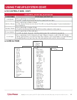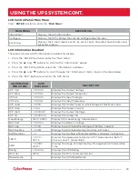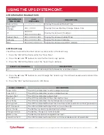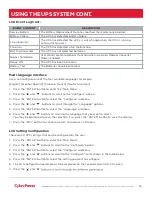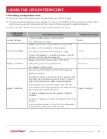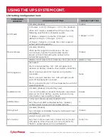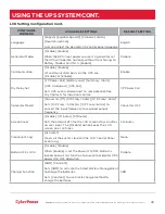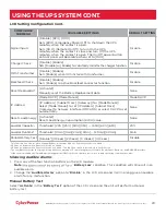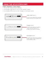
įĂĀĂĀƫ5!.ƫ+3!.ƫ5/0!)/ƫĨĩČƫ *ċƫ((ƫ.%#$0/ƫ.!/!.2! ċƫ((ƫ+0$!.ƫ0. !).'/ƫ.!ƫ0$!ƫ,.+,!.05ƫ+"ƫ0$!%.ƫ.!/,!0%2!ƫ+3*!./ċƫ
32
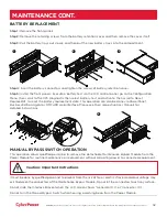
BATTERY REPLACEMENT
Step 1:
Remove the front panels.
Step 2:
Remove the retaining screws from the battery retention cover and then remove the cover itself.
Step 3:
Pull the battery trays out slowly and then put the new battery trays into the compartment.
Step 4:
Insert the battery connectors and tighten the screws of battery retention cover.
Step 5:
Install the front panels. Execute a battery test via the LCD control panel, go to the Configuration
Menu, then scroll to the UPS Diagnostic then select battery test and Activate, then scroll to Reset
ReplaceBAT to reset the battery replacement date. This operation can also be done via PowerPanel®
Business Edition Agent or RMCARD web interface. Please see their respective User Manuals for
detailed instructions.
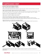
MANUAL BYPASS SWITCH OPERATION
This operation allows qualified personnel to remove the detachable Maintenance Bypass Module from the
Power Module for routine maintenance or replacement without disrupting power to connected equipment.
It must be done by qualified personnel to prevent from the risk of fire or electric shock. Hazardous voltage may
exist between the connectors of the Maintenance Bypass Module. Do not let the connectors touch any surface.
Do not slide the Interlock Bracket when the LCD screen shows “Generator On” or “Converter On”.
Do not turn the Manual Bypass Switch when hearing a warning beep from the Power Module.
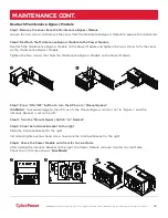
MAINTENANCE CONT.
1
2
3
4
5
Caution: Important Instructions

