įĂĀĂĀƫ5!.ƫ+3!.ƫ5/0!)/ƫĨĩČƫ *ċƫ((ƫ.%#$0/ƫ.!/!.2! ċƫ((ƫ+0$!.ƫ0. !).'/ƫ.!ƫ0$!ƫ,.+,!.05ƫ+"ƫ0$!%.ƫ.!/,!0%2!ƫ+3*!./ċƫ
17
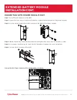
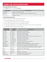
CONNECTION WITH POWER MODULE CONT.
Step 1:
Turn off the DC breaker on the EBM.
Step 2:
Loosen the two screws to remove the battery cable retention bracket of the power module.
Step 3:
Use the output cable of the EBM to connect the EBM to the Power module.
Step 4:
Rotate the battery cable retention bracket and tighten the two screws to fix battery cable.
Step 5:
Use a power cord to plug AC input inlet of the battery module into a wall receptacle.
Step 6:
Turn on the DC breaker of the EBM.
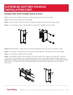
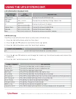
Connection #2: Power module with multiple battery modules
1
2
OFF
4
6
ON
$&287387
&KDUJH2QO\
$&,1387
$
9a
)86(
3/8*,172$
:$//
5(&(37$&/(
5(/$<
287387
287
,1
86%
56
)86(
9a
$
$&,1387
&KDUJH2QO\
287
287
%
$&.
)
(
('
3
527
(&7
,2
1
&
211
(&
725
%$
77
(5
<
,1
387
9
(
32
,17(5)$&(
$&287387
9
%$77(5<,1387
%$77(5<287387
9
%
$&.
)
(
('
3
527
(&7
,2
1
&
211
(&
725
%$
77
(5
<
,1
387
9
(
32
,17(5)$&(
9
%$77(5<287387
%$77(5<,1387
9
EXTENDED BATTERY MODULE
INSTALLATION CONT.


