Page18
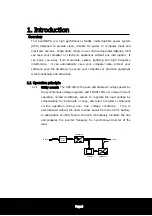
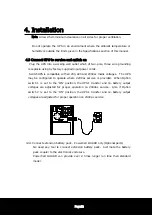
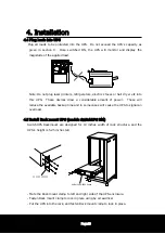
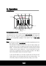
5. Operation
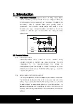
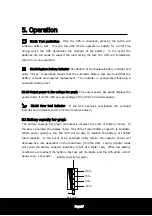
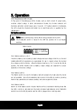
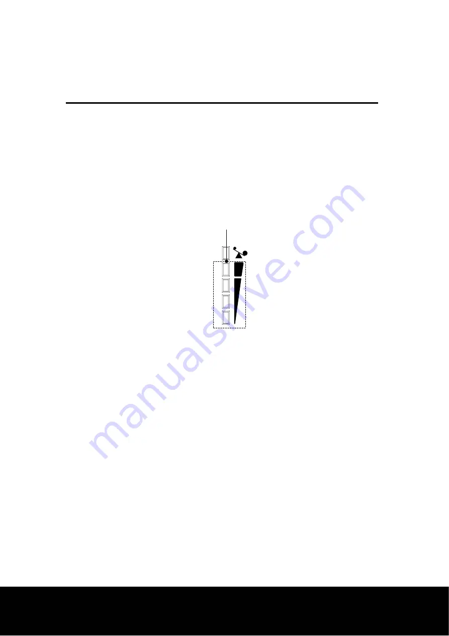
5.3 Output power bar graph
The output power bar graph displays the power drawn from the UPS as a percentage of
the UPS
’
s full rated capacity. This example shows that the load equipment is drawing
between 75% and 100% of the rated capacity. When the UPS is loaded such that four
bar illuminated, thoroughly test your complete system to be sure the UPS will not
become overloaded. A thorough test includes running backup tape drives, disk drives,
etc. If the UPS becomes overloaded, the overload bar will illuminate and the UPS will
sound an alarm.
Load Level
Output bar graph
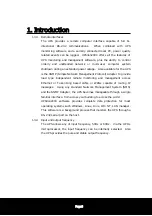
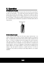
5.4 Line voltage bar graph
The line voltage bar graph displays the UPS
’
s input voltage in discrete steps. Line
voltage is displayed when the On/Test and Alarm disable pushbutton are pressed and
held. The example above shows that the UPS
’
s input line voltage is between 210 and
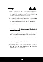
229 Vac. If no bars are illuminated, and the UPS is plugged into a known working wall
outlet, the line voltage is extremely low. Low input voltage could be a result of an
overloaded branch circuit, a misadjusted service pole transformer or intentional local
service brownout. The UPS will compensate for this problem by boosting the load
voltage supplied to your computer equipment. If all four bars are illuminated, the line
voltage is high and should be checked by a qualified electrician. The UPS will
compensate for this problem by trimming the load voltage supplied to your computer
equipment.


