Page14
5. Operation
5.1 Display features
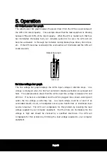
5.1.1 Enable/Switch on the UPS
The Enable/On switch is used to control activation of the UPS and to energize the load
when Option switch 5 is set to the ON (I) position (See section 5.6). When shipped, this
switch is in the
“
OFF
”
position to prevent accidental activation of the UPS. The
batteries will not appreciably discharge if this switch is left
“
ON
”
(See section
3.2/3.4/3.5).
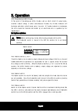
Note:
The UPS may be configured to operate on Auto starting mode (Option switch 5 is
set to the ON (I) position. See section 5.6.
Once powered, all indicators will blink, and the UPS will initiate a battery test.
During the test, the UPS will operate the load from power derived from the
battery. This test function ensures that the UPS is working properly and that
its battery does not require replacement. The test will take about 15 seconds,
and the test is completed when the On Line indicator illuminate. After battery
test, the UPS
’
s battery charger will be started if required.
In the event the batteries are too weak to support the load during the test,
trouble indicator will be illuminated, and the UPS emits continuous beeps. The
UPS
’
s battery charger will operate when the utility voltage is over 154Vac
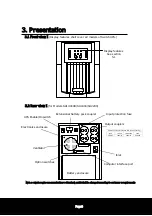
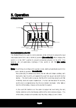
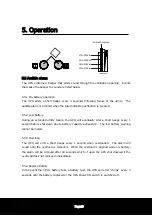
TEST
Load Level
Batt. Level
AutoBoost indicator
On-line indicator
AutoTrim indicator
Battery bar graph
Low battery indicator
Trouble indicator
Alarm disable pushbutton
On battery indicator
On/Test pushbutton
Replace battery indicator
Output power bar graph
Over load indicator


