6
DO NOT
REMOVE THE GROUND
PIN ON THE PLUG OR IN ANY WAY
BYPASS, MODIFY, DEFEAT, OR
DESTROY THE GROUNDING
SYSTEM OF THE VENDING
MACHINE
•
DO NOT USE WITH AN EXTENSION CORD.
•
DO NOT
REMOVE THE WARNING TAG
ATTACHED TO THE POWER SUPPLY CORD.
•
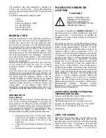
The GFCI must be tested frequently and before
each use in accordance with the instructions
provided on the GFCI device.
IF THE GFCI
DOES NOT PASS THE TEST, DO NOT USE
THE MACHINE
. Unplug the supply cord from the
receptacle and call the Crane Merchandising
Systems Technical Support Group for assistance
at 1-803-266-5001.
It is recommended that the machine be located so that
the GFCI device will be accessible after the machine
is installed. After installation, visually inspect the
GFCI and power supply cord to be sure it is not
crushed, pinched, or stretched.
Protect the power supply cord during transportation
and use. Periodically inspect the power supply cord
for damage. If the cord or plug is worn or damaged, it
must be replaced with a power supply cord of the
same type, size and specification as originally
provided with the machine.
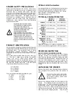
DO
NOT USE THE
VENDING MACHINE UNTIL THE WORN OR
DAMAGED CORD IS REPLACED.
FAILURE TO COMPLY WITH
THESE INSTRUCTIONS MAY
SUBJECT THE USER TO THE RISK
OF INJURY OR ELECTRICAL
SHOCK WHICH CAN BE SERIOUS
OR FATAL. PERIODICALLY
INSPECT THE POWER SUPPLY
CORD FOR DAMAGE. IF THE
CORD BECOMES DAMAGED IT
MUST BE REPLACED WITH THE
SAME SIZE AND TYPE CORD.
CONTACT CRANE
MERCHANDISING SYSTEMS FOR
ASSISTANCE.
INSTALLATION AND SETUP
INSTRUCTIONS
ELECTRONIC LOCK
The electronic lock provided in the vender consists of
a door mounted, motor driven 2 point latching system,
cabinet mounted latch and strike system, an infrared
controlled CPU, and a remote control key (FOB). The
design is modular and allows for easy field service.
The electronic remote key (FOB) features a rolling
code system which cannot be decoded if it is lost or
stolen. After the vender has been unlocked, a new
key can be programmed into it any number of times.
If a key is lost or stolen, it is recommended you
change the lock code in the field as soon as possible.
Changing the lock code requires a new key and
pressing the PROGRAM button on the lock inside the
vender. The lock does not need to be changed for re-
keying.
Important:
For security reasons all Electronic
Door Lock Venders are shipped less
keys. Customers will need to contact
the Electronic Door Lock
manufacturer to order keys.
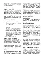
A power bypass connector, located in the product
delivery port, allows auxiliary power to be applied via
a battery pack to the electronic lock in the event that
power is not available or there has been a failure of
the internal power supply. In the event of an
emergency, battery power is applied to the connector
and the door can be opened and closed using the
FOB.
The electronics uses an infrared transmission system,
which functions similar to a television remote control.
The transmission signal is line-of-sight, which requires
you to aim the remote at a specific place at close
range to prevent the accidental opening of several
venders at the same time.
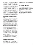
TO OPEN THE ELECTRONIC DOOR LOCK:
1. Plug the vender into a properly powered
outlet.
2. Hold the key FOB 0 to 3” (76.2 mm) in front of
the Delivery Port Door and press the button
on the key FOB.
Note: The wide end of the FOB should face
the door.
3.
The lock will begin releasing the door. The
display will indicate
OPENED.
After the motor
has stopped running, you can pull the door
open.
TO CLOSE THE ELECTRONIC DOOR LOCK:
CAUTION: DO NOT SLAM THE DOOR CLOSED.
Slamming the door closed can damage the electronic
locking device.
1. Push the door to the cabinet until the lock
motor starts. The display will indicate:
CLOSED
2. Continue to push the door for approximately 2
to 3 seconds after the lock motor starts. The
lock will pull the door closed tightly.
3. When the lock motor stops the door will be
locked. Before leaving the vender, ensure
that the door is locked.
Содержание BevMax 4
Страница 2: ...1 ...
Страница 69: ...68 ...
Страница 70: ...69 MACHINE FRONT VIEW 6A 9 11 13 14 5B 5A 7 3A 4B 19 18 6B 3C 4B 4A 2 4C 17 16 1 12 20 ...
Страница 72: ...71 CABINET DETAIL PRODUCT AREA 3 2B 12 9 6 7 2A 8 5 14 11 ...
Страница 74: ...73 CABINET DETAIL SERVICE DOOR AREA 1 16 10 4 7 11 5 17 11 4 5 20 22 21 14 12 2 10 15 8 ...
Страница 78: ...77 DELIVERY PICKER CUP ASSEMBLY 11 1 2 21 10 5 16 14 15 17 4 7 12 13 19 6 19 20 9 8 19 3 22 ...
Страница 80: ...79 SERVICE DOOR OUTSIDE 3 1 4 12 18 20 25 5 7 8B 8B 23 9 15 14 18 17 8A 21 16 13 26 19D 19B 6 10 24 27 ...
Страница 82: ...81 SERVICE DOOR INSIDE 1 5 10 3 11 25 6 2 25 35 9 15 14 10 17 34 19 23 24 20 9 4 5 18 21 22 8B 26 29 7 8A ...
Страница 84: ...83 GATE TRAY DETAIL 8 3 7 11 1 2 4 6 12 13 14 10 9 ...
Страница 92: ...91 REFRIGERATION UNIT BevMax 4 with Metal Evap Box prior to 9539 0032DJ 26 2 10 18 13 11 15 28A 28C 6 16 9 27 ...
Страница 94: ...93 ELECTRONICS Pepsi Generic BevMax 4 EXE Control Boards 3 1 7 5 4 6 7 Executive 4 pin interface added ...
Страница 96: ...95 HARNESSES 8 2 10 1 4 9 3 6 7 11 24 18 17 12 21 16 23 19 20 15 25 26 22 5 ...
Страница 98: ...97 ...


