24
“CONSUMER OVERPAY OFF (ON), Press “
” -
turn ON (OFF)” will show on the display. Press the
“
” Key to toggle setting and press CLR return to
“Consumer Overpay”. Press the “CLR” key to return
to “SETUP MODE 1” or press the “A” key to advance
to the next menu item below.
DATE/TIME
- Press key “5”
Shows the year, month, date, and time setting
currently in the system in following format: 2005 Apr
28 15:45. Setting the day, date, and time is covered
in the INITIAL PROGRAMMING section of this
manual. Press the “CLR” key to return to “SETUP
MODE 1”.
TOTAL SALES
-
Press key “6”
Shows total sales since machine manufacture. This
total is not cleared by CLEAR TOTALS. Press the
number “6” on the keypad, the display will show
“TOTAL SALES” press the “
” Key and “Sales: ###
and Vend ### totals will show on display. Press the
“CLR” key to return to “Total Sales”. Press the
“CLR” key to return to “SETUP MODE 1” or press
the “A” key to advance to the next menu item below.
HEALTH CONTROL
-
Press key “7”
Allows the service technician to select items to
ENABLE HEALTH CONTROL. When enabled, if the
temperature in the vender does not reach 41º F (5º
C) within 30 minutes after the service door is closed,
a “HEALTH TIME” error will occur and lockout the
enabled selection(s) from vending until after the
error is cleared. Also, if the temperature in the
vender goes above 41º F (5º C) for more than 15
minutes after the initial cool down period, a
“HEALTH CONTROL” error will occur and lockout
the enabled selection(s) from vending until the error
is cleared. Press the number “7” on the keypad and
the display will show “HEALTH CONTROL”. Press
the “
” key and the display will show ‘ENTER
SELECTION”. To set:
1.
All selections.
Press the “
” key and
display will show “Disabled (Enabled)
Continue?
= Y CLR = N. When enabled
all selections in the vender will now be set
for health control. Press CLR to show all
selections assigned. Then press CLR and
the display will change to “ENTER
SELECTION”. Press CLR to return to
“HEALTH CONTROL”.
2. One
tray.
Pressing the letter of the shelf
followed by the “
” key and display will
show “Disabled (Enabled) Continue?
= Y
CLR = N. When enabled all selections on
that shelf will now be set for health control.
For example, to control the A shelf push key
“A” followed by “
” key. The display will
change to “ENTER SELECTION”. Press
CLR to display all selections assigned then
press CLR to return to “HEALTH
CONTROL”.
3. Single selection.
Pressing the desired
selection followed by the “
” key and
display will show “Disabled (Enabled)
Continue?
= Y CLR = N. When enabled
desired selection will now be set for health
control. For example, to control the A1 push
keys “A1” followed by “
” key. The display
will show “Disabled (Enabled)” etc… Press
CLR to display all selections assigned then
press CLR to return to “HEALTH
CONTROL”.
Priority will be given to the higher ranked method. If
one selection on the A tray was set to ENABLE
using option 3 above and you wish to change the
remaining selections on that tray using option 2, the
Setting for the entire tray would take precedence.
Conversely, if the tray was set using option 2 first
followed by the single selection using option 3, the
setting for the remainder of the shelf would remain
and the new price for the single selection would
change to the new value. Press “CLR” to return to
“SETUP MODE”.
UPDATE SOFTWARE
-
Press key “8”
(PASSWORD REQUIRED)
Allows the service technician to manually load
software if needed. New software automatically
loads on power up.
Caution
: If this mode is entered
with no EPROM installed in controller, it will cause
control board failure. The following information
describes how to update software. All new software
revisions will automatically update the software
revision in the control board.
Important
: EPROM’s
containing software are sensitive to Electrostatic
Discharge (ESD). Failure to handle the Eprom
carefully could cause damage, which may result in a
failed control board.
ALWAYS KEEP THE EPROM
IN THE ESD TUBE. GROUND YOURSELF ON THE
VENDER CABINET BEFORE REMOVING THE
EPROM FROM THE ESD TUBE OR CONTROL
BOARD. AN EPROM CAN BE USED TO
PROGRAM MANY VENDERS, AS LONG AS
CARE IS TAKEN NOT TO DAMAGE THE
EPROMS LEGS.
ALWAYS TURN POWER OFF
BEFORE REMOVING OR INSTALLING EPROMS
IN THE CONTROL BOARD.
Important Notes: Use
the programming section of the manual to program
the vender.
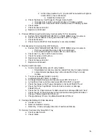
2. EPROM
Removal:
a. Power down the Vender. Ground
yourself on the vender cabinet
before removing the EPROM from
the ESD tube or control board.
b. If an Eprom is present in the control
board, remove the existing Eprom.
i. Note; An Eprom does not
need to be in the control
Содержание BevMax 4
Страница 2: ...1 ...
Страница 69: ...68 ...
Страница 70: ...69 MACHINE FRONT VIEW 6A 9 11 13 14 5B 5A 7 3A 4B 19 18 6B 3C 4B 4A 2 4C 17 16 1 12 20 ...
Страница 72: ...71 CABINET DETAIL PRODUCT AREA 3 2B 12 9 6 7 2A 8 5 14 11 ...
Страница 74: ...73 CABINET DETAIL SERVICE DOOR AREA 1 16 10 4 7 11 5 17 11 4 5 20 22 21 14 12 2 10 15 8 ...
Страница 78: ...77 DELIVERY PICKER CUP ASSEMBLY 11 1 2 21 10 5 16 14 15 17 4 7 12 13 19 6 19 20 9 8 19 3 22 ...
Страница 80: ...79 SERVICE DOOR OUTSIDE 3 1 4 12 18 20 25 5 7 8B 8B 23 9 15 14 18 17 8A 21 16 13 26 19D 19B 6 10 24 27 ...
Страница 82: ...81 SERVICE DOOR INSIDE 1 5 10 3 11 25 6 2 25 35 9 15 14 10 17 34 19 23 24 20 9 4 5 18 21 22 8B 26 29 7 8A ...
Страница 84: ...83 GATE TRAY DETAIL 8 3 7 11 1 2 4 6 12 13 14 10 9 ...
Страница 92: ...91 REFRIGERATION UNIT BevMax 4 with Metal Evap Box prior to 9539 0032DJ 26 2 10 18 13 11 15 28A 28C 6 16 9 27 ...
Страница 94: ...93 ELECTRONICS Pepsi Generic BevMax 4 EXE Control Boards 3 1 7 5 4 6 7 Executive 4 pin interface added ...
Страница 96: ...95 HARNESSES 8 2 10 1 4 9 3 6 7 11 24 18 17 12 21 16 23 19 20 15 25 26 22 5 ...
Страница 98: ...97 ...

