background image


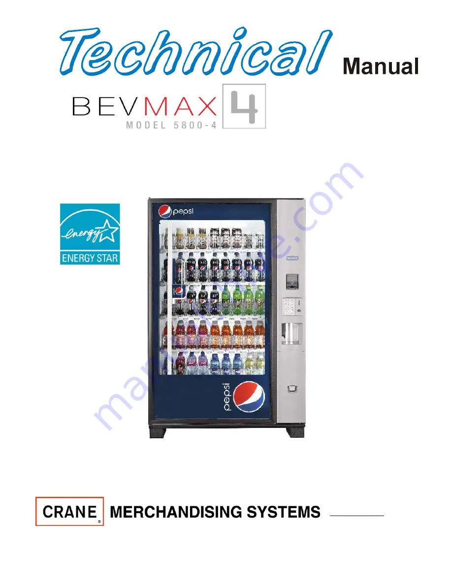
Glassfront Vender 

Models DN5800-4, DN5800-E4, DN3800-4, DN3800-E4 
Production Run 8882AH & higher 


Manufactured by 


Crane Merchandising Systems 
P.O. Drawer 719 
Williston, SC  29853-0719 
803-266-5001 
fax: 803-266-5049 
Visit us on the web:  

www.dixienarco.com


803,904,640.21 


Operation 
Service 
Parts 
Troubleshooting 
Manual


Tier 2


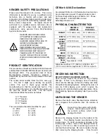
Содержание BevMax 4

Страница 1: ...3800 E4 Production Run 8882AH higher Manufactured by Crane Merchandising Systems P O Drawer 719 Williston SC 29853 0719 803 266 5001 fax 803 266 5049 Visit us on the web www dixienarco com 803 904 640 21 Operation Service Parts Troubleshooting Manual Tier 2 ...

Страница 2: ...1 ...

Страница 3: ... 9 Double Gate Assembly 9 10 Slide Pusher Assembly 10 Deliver Picker Cup Assembly 10 Refrigeration Deck Clamp Assembly 10 Belt Tensioning Adjustment Components 10 PROGRAMMING 11 30 General 11 External Display Items 11 Normal Operation Messages 11 Initial Programming 11 12 Quick Reference Menu Items 13 14 Service Mode 15 17 Test Mode 17 22 Setup Mode 1 22 25 Setup Mode 2 25 27 Setup Mode 3 27 28 Sa...

Страница 4: ...D Lighting Export only 61 Vender Wiring Diagram Power LED Lighting Domestic only 62 Compressor Parts Diagram Domestic 63 Compressor Parts Diagram Export 64 AC Distribution Box Connector Voltages Domestic 65 AC Distribution Box Connector Voltages Export 66 PARTS LIST AND DIAGRAMS 67 102 Machine Front View 69 70 Cabinet Detail Product Area 71 72 Cabinet Detail Service Door Area 73 74 XY Motor Picker...

Страница 5: ...009 L 2013 I 2010 M 2014 J 2011 N 2015 K 2012 O 2016 CE Mark IIA Declaration An updated CE Mark or IIA Declaration document can be provided upon request If needed please contact Technical Support Manager in Williston SC Phone Bryan Staubs 1 803 266 8805 or email bstaubs cranems com PHYSICAL CHARACTERISTICS DN5800 4 DN5800 E4 DN3800 4 DN3800 E4 HEIGHT 72 1828 8 mm 72 1828 8 mm WIDTH 47 1193 8 mm 39...

Страница 6: ...is is 120Vac 60Hz 1P In Europe Australia and other export countries this is 220 230 240Vac 50Hz 1P depending upon your country voltage The serial plate also specifies the ampere rating of the machine This machine must be plugged into a properly rated receptacle with its own circuit protection fuse or circuit breaker Equipment Nominal Power Requirements 120V 10 2 A 1224W 1 224kw 220V 5 8 A 1276W 1 ...

Страница 7: ...e decoded if it is lost or stolen After the vender has been unlocked a new key can be programmed into it any number of times If a key is lost or stolen it is recommended you change the lock code in the field as soon as possible Changing the lock code requires a new key and pressing the PROGRAM button on the lock inside the vender The lock does not need to be changed for re keying Important For sec...

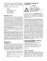
Страница 8: ... harness located on the front of the power box Locate the control board mounted on the rear wall Remove the battery from its holder B1 PLACING THE VENDER ON LOCATION CAUTION DO NOT TRANSPORT THE VENDER TO OR FROM THE LOCATION LOADED WITH PRODUCT OR DAMAGE TO THE VENDER MAY RESULT The vender is intended for INDOOR USE ONLY It should be kept out of direct sunlight and away form any heat source This ...

Страница 9: ...driver which product the column is set for To install the flavor card simply detach it from the sheet at the perforation and slide it into the slots in the product pusher Contact your graphics supplier to purchase as needed COIN CHANGERS OTHER ACCESSORIES The vender can have an MDB coin changer installed and can have an MDB bill acceptor installed as well Note BevMax 4 5800 4 3800 4 will work with...

Страница 10: ...ar wall inside the service area It is flash programmable and may or may not include the program chip EPROM which controls all aspects of the vender It also contains the power supply which regulates the voltages required to operate the motors as well as the coin mechanism digital display and all logic functions in the vender KEYPAD The keypad is located on the front of the service door It consists ...

Страница 11: ...gainst each other and are allowed to progress into the gate area Periodic cleaning and lubrication of the slides is recommended DO NOT USE SOLVENTS OR ABRASIVE MATERIALS TO CLEAN ANY PORTION OF THE TRAY DELIVERY PICKER CUP ASSEMBLY The delivery picker cup assembly is located on the XY vend mechanism Its purpose is to pick the product from the column and deliver the product to the delivery port ass...

Страница 12: ...e software version in use as Software i e 700 91 followed by the default idle message ENJOY A REFRESHING DRINK or ENJOY A REFRESHING DRINK AND SNACK when attached to a snack vender INITIAL PROGRAMMING DATE TIME To set date time enter SETUP MODE 1 by opening the service door and pressing the Service Button three 3 times Press the number 5 and DATE TIME will show on display Press the key and display...

Страница 13: ... the display will show SET NOT AVAIL TIME Press the key and the display will show Select Block 1 4 Press number 1 Key to set Select Block 1 available settings Key 2 for Select Block 2 etc Once you select the Select Block you wish to set the display will show Start MTWTFSS Stop 1 00 00 NNNNNNN 00 00 with the start time hour highlighted Press the numbers to enter the hour you wish to start select bl...

Страница 14: ...uild number B Model Set Model Number DN5800 4 DN3800 4 DN5800 E4 DN3800 E4 E Extended Cup All BevMax 4 5800 4 Enabled F Delivery Picker Cup Sensor Option BevMax 4 5800 4 with cup sensor set ON BevMax 4 5800 4 with out cup sensor set OFF 1 Position Test F goes home 0 cycles plunger stops all motors Shelf letter moves cup to shelf selected Column moves cup to column selected 2 Port Test A opens port...

Страница 15: ...es cup to shelf selected Column moves cup to column selected 2 Port Test A opens port B closes port C sensor test ON D sensor test OFF E cup LED s on F port LED s on All Stop 3 Delivery Picker Cup Check On status of cup sensor In detects product in cup Out picker out switch status Hm picker home switch status 4 Repeat Vend 5 Vend Error Codes Factory Use Only Do Not Use 6 Product Sensors All BevMax...

Страница 16: ...g the current setting temperature will be displayed Press F for Fahrenheit or C for Celsius Press the Key to save and return to Display Temperature Press the CLR key to return to SERVICE MODE or press the A key to advance to the next menu item below SET REFRIG TEMP Press Key E Allows the service technician to set the average product temperature set point for initial pull down and reload recovery P...

Страница 17: ...he CLR key to return to SERVICE MODE or press the A key to advance to the next menu item below FORCE VEND Press key 5 Forces the customer to make a vend by inhibiting the coin return lever once the minimum vend price line has been met or exceeded The coin return lever will not be inhibited if there is not enough credit to vend the lowest priced item or if a vend failure has occurred Factory settin...

Страница 18: ...eturn to SERVICE MODE or press the A key to advance to the next menu item below RELAY TOGGLE Press key 9 Allows the service technician to test the Light Relay Fan Relay and Compressor Relay Press the number 9 on the keypad and the display will show Relay Toggle Press the Key and display will show Light A On or Off Fan B On or Off Compressor C On or Off Display will show current status of the relay...

Страница 19: ... toggle the menu on or off KEYPAD TEST Press key E Allows the service technician to test any or all keypad keys Press the letter E on the keypad and the display will show KEYPAD TEST Press the key and the display will show Keypad Test then press each key on the keypad Each key pressed will show on the display until the CLR key is pressed The display will return to Keypad Test Press the CLR key to ...

Страница 20: ... on any of these tests Key 3 Delivery Cup Check Press the number 3 key and the display will show On 0 In 0 Out 0 Hm 1 Note The door switch or left door switch on e lock venders must be pulled to the out position to perform this test Caution XY needs to be in the home position before performing this test Press the key and the display will show Port Sensor On Off On 0 In 0 Out 0 Hm 1 Press the key t...

Страница 21: ...position then move back to the swipe position again Press the key to send the Delivery Cup Assy back to the Home position and the programming will return to Factory Diagnostics Press CLR key to return to Test Mode Then go to Test Vend and test for proper delivery of product in the Port Assy of the Service Door Press the CLR key to return to Factory Diagnostics Press the CLR key to return to TEST M...

Страница 22: ... Key and Door Opened Times Month YEAR will show on display This is the number of times the service door has been opened since the last CLEAR TOTALS or MASTER RESET and the time day and date of the last opening Press Key A to see the time of the 5 previous openings Press the CLR key to return to Door Open Press the CLR key to return to TEST MODE or press the A key to advance to the next menu item b...

Страница 23: ... message to replace the default idle message Press the letter B on the keypad and ENTER MESSAGE will show on the display Press the key and Edit Idle Message Enjoy a Refreshing Drink will show on display with the first character on the left highlighted The program is now ready to accept the new message The A key will move forward through the alphabet numbers space punctuation marks AND an L The B k...

Страница 24: ...D DEX PASSWORD 000000 DOOR OPEN TIME CLEARED POWER OUT TIME CURRENT TIME STORAGE TEMP 57º F 13 8º C REFRIG TEMP 37º F 2 7º C CONSUMER OVERPAY OFF MACHINE NUMBER Press key 1 PASSWORD REQUIRED Allows assigning a user number to the machine for audit and or inventory control requirements Press the number 1 on the keypad and MACHINE NUMBER will show across the display and then change to the number curr...

Страница 25: ... A shelf push key A followed by key The display will change to ENTER SELECTION Press CLR to display all selections assigned then press CLR to return to HEALTH CONTROL 3 Single selection Pressing the desired selection followed by the key and display will show Disabled Enabled Continue Y CLR N When enabled desired selection will now be set for health control For example to control the A1 push keys A...

Страница 26: ...k can now be programmed into the system All times must be entered in military time format 24 hour clock Set Lights Off Time can be set the same way as Set Not Available Time in the Initial Programming section of the manual ENTER NEW PASSWORD Press key 0 PASSWORD REQUIRED Allows the service technician to enter a 4 number personalized password IF YOU DECIDE TO CHANGE FROM THE DEFAULT PASSWORD PLEASE...

Страница 27: ...e to Sales is enabled the product column will be removed form the Space to Sales rotation and the VMC will attempt to vend from the next column in the Space to Sales block If the vender is unable to vend any products from a Space to Sales block the customer s credit will be returned and the entire block will be marked as SOLD OUT Press the F key on the keypad The display will show SET NOVEND LIMIT...

Страница 28: ...owing the state you wish the mode to be in press the CLR key to return to Double Talk Press CLR to return to SETUP MODE 2 SET STORAGE TIME Press key 9 This function is used set the Time Date and Day when Storage Temperature will be ON Press the number 9 and SET STORAGE TIME will show across display Set Storage Time can be set in the same manner as SET NOT AVAIL TIME covered in the Initial Programm...

Страница 29: ...l be when price holding mode is enabled Press the letter E on the keypad The display will show VIEW PL ASSIGNMENTS Press the Key to view on display and scroll through the price line assignments Press the CLR to exit to VIEW PL ASSIGNMENTS Press the CLR key to return to SETUP MODE 3 or press the A key to advance to the next menu item below VIEW PL VALUE Press key F This menu allows the user to see ...

Страница 30: ...show Regular XX XX Enter the desired price using the selection keypad the display will change to PR XX XX with XX XX being the price you just entered Press the key a will appear under PR on the display Enter the selection number on the keypad Press the key the display will ask Price XXX ok Press the key to accept and continue entering selections at that price or press the CLR key to go back one st...

Страница 31: ...bling or disabling a range shelf or the entire machine The setting will change to the opposite of the lowest selection number in the range shelf or machine being set For example if you are changing the top shelf and selection 210 is set to enable while 212 216 are set to disable then you would be disabling the top shelf from Golden Eye because the lowest selection number on the shelf was set to en...

Страница 32: ...ne Merchandising Systems Technical Support Group for assistance at 1 803 266 5001 CAUTION REMOVE POWER TO THE AC DISTRIBUTION BOX BEFORE CLEANING OR WHEN ANY ELECTRICAL COMPONENTS ARE CONNECTED DISCONNECTED FOR TESTING OR REPLACEMENT CLEANING DO NOT USE A WATER JET OR NOZZLE TO CLEAN THE VENDER GLASS DOOR The display glass should be cleaned inside and out with paper towels and glass or non abrasiv...

Страница 33: ...RCUIT IS ALWAYS LIVE WHEN THE PLUG IS CONNECTED TO AN ELECTRICAL OUTLET REFRIGERATION CONDENSER Clean the condenser periodically of dirt or lint build up Remove the build up with a brush or vacuum or blow the dirt out of the condenser with compressed air and approved safety nozzle Ensure nothing obstructs air intake at the bottom of the main door Ensure nothing obstructs air exhaust at the rear of...

Страница 34: ...coder J5A J5 DEX P15 X Motor Encoder J11A J11 Keypad P2 Product Port J12A J12 Temp Sensor P6A P6 Display J16 Multi Drop Bus P7A P7 Relays U17 EPROM Socket P8 Y Cup Motors P3 Door Switch XY P10A P10 Door Switch B1 Battery J2 Supplier Programming Connector S1 Service Switch P31 Executive Interface J3 Dongle Harness P1 J12A J5A P6A J11A J16 J3 J2 F1 U17 P3 BevMax 4 DN5800 4 5800 E4 DN3800 4 3800 E4 S...

Страница 35: ...et 2 Defective gear box 3 Defective follower ii Occurs on entire shelf 1 Shelf not secured on supports 2 Position alignment iii Occurs on same column multiple shelves A2 B2 C2 D2 E2 1 Shelf not secured on supports 2 Position alignment 3 Plunger did not cycle fully a Replace delivery cup assembly b Replace control board ii Gate did actuate 1 Product and gate mismatch 2 Possible delivery cup assembl...

Страница 36: ...green LED on the control board b At the home position the X top far left home switch will light an amber LED on the control board i Adjust the X drive belt at the bottom left belt clamp b Check dynamic tensioner i On rear belt it should be 6 from the bottom ii If one is installed on the front belt it should be 6 from the top 4 Elevator will not move vertically a Perform TEST VEND POSITION TEST in ...

Страница 37: ...or syrup or dirt build up d Replace port assembly e Check harness and motor f Replace control board 8 Double Vend From Gate a Is correct gate assembly used in early models i Small diameter cans may only be vended from tray A in early models ii Large diameter packages may not be vended from tray A in early models b Too many packages loaded in column c Is software 804 927 700 91 or higher d Is Plung...

Страница 38: ...connected to control board NO YES Plug in connector Plug in Vender Manually move XY to HOME position In position test are the Red Yellow Green LED s on control board illuminated YES NO Yellow light X Axis Home Red light Plunger Home Does XY move to HOME position using Key Pad YES NO Change Control Board Change failed Motor RED light is ON OFF Red Light Plunger Home Visually confirm plunger in home...

Страница 39: ...E NOT HOME In position test Press 0 key to cycle plunger Is Red LED ON OFF Cycle plunger multiple times to ensure proper operation If Plunger is stuck in the out or in position Refer to Delivery Picker Cup Troubleshooting or replace Cup Assembly Plunger Home Red light ON OFF ...

Страница 40: ...heck repair replace harness Problem solved YES NO Replace control board Check belt and pulley Is the Yellow LED on YES NO Do a Vend Test with Door Closed Is the display showing Encoder count with a 1 at the end of the X Axis code YES NO 1 1 X axis Y axis 1 showing a switch or ground wire issue 0 showing a mechanical obstruction NO YES Check replace motor Problem solved YES NO X Axis Home Yellow li...

Страница 41: ...o a Vend Test with Door Closed Is the display showing Encoder count with a 1 at the end of the Y Axis code YES NO 1 1 X axis Y axis 1 showing a switch or ground wire issue 0 showing a mechanical obstruction NO YES Check replace motor Problem solved YES NO Y Axis Home Green light ON OFF Manually move cup to A9 and pull top door switch out Press the F key Picker Cup goes to the home position YES NO ...

Страница 42: ...on go to appropriate Trouble Shooting Pages If off 0 showing is a mechanical obstruction Check replace motor as needed Problem solved NO YES Pull top door switch out Press the F key Picker Cup goes to the home position YES NO Do a position test Run Y axis A to E X axis 2 to 7 five times each Does Picker Cup stop in correct position YES NO Do a vend test with door closed While running does the Gree...

Страница 43: ...ger cycle YES NO Remove Cup bottom cover Is motor plugged in YES NO Press 0 key Is there power to the motor for 1 second between 20 30 VDC NO YES Check repair or replace plunger spring plunger in and out switches Replace motor Trouble shoot Y motor system See pg 38 Check fuse on board Good Failed Check top door switch working NO YES Replace switch Verify Y Home switch toggles green light on off YE...

Страница 44: ...Axis E chain Ground wire Send cup to A shelf Is cup in correct location YES NO Fire the plunger to ensure correct location Repeat A E cycle two to three times Is cup in correct location YES NO Repeat A E cycle two to three times Does cup position get worse YES NO Go to Factory Diagnostics and check Offset Adjustment and adjust as necessary See programming section of manual CUP AT WRONG LOCATION HI...

Страница 45: ...t position YES NO Is the horizontal alignment correct YES NO See X Axis TS Adjust Shelf Offset as required See programming Check Harness Keypad Motor Board See XY not working page 34 Check Harness Keypad Motor Board Do a Keypad test Works YES NO CUP AT WRONG LOCATION LEFT RIGHT or X AXIS Repeat test at several locations Does it stop in correct position NO YES Close door do a test vend Change Keypa...

Страница 46: ... YES NO PORT DOOR TEST SWITCH CODES Position A Open switch yellow LED on control board Position B Close switch Green LED on control board Position C Vend sensor on off Position D Vend detect Red LED on if it sees something in port only if C is 1 vend sensor on Use Factory Diagnostics to open the delivery port door Is the yellow LED on control board on and Port Door open switch code is 1 YES NO Che...

Страница 47: ... Recommendation 4 Replace Coin Mech DOLLAR BILL ACCEPTANCE ISSUES PROBLEM CAUSE FIX Bill Validator will not run Prices tube cash conditions Check Mech Tubes Takes Bill in Then Rejects it Check Validator or Replace Stacks Bill While in Escrow Mode Max Price Not Yet Reached Bill Error Listed in Test Mode Communication Error with Bill Validator Bill Validator Reported Error Takes Bill Gives No Credit...

Страница 48: ...F Disconnected Apply power Blown Fuse Check fuses and replace if necessary Loose connection Check cable at coin mech and controller board Jammed coin mechanism Clear coins Weak springs on changer gate COINCO units only Replace spring Gate partially open Clean and reset gate If COINCO unit check spring Dirty faulty coin sensor Clean Replace Incompatible coin mechanism Replace Defective coin mechani...

Страница 49: ... to determine cause of Out Of Service Refer to programming for error explanations Loose connection Check cable at bill validator and controller board Coin mechanism low on coins Fill coin tubes Bill path obstructed dirty Clear clean path Wrong option switch settings Reset Incompatible bill validator Replace Defective bill validator Replace Defective controller board Replace ...

Страница 50: ...D Incorrect change dispensed Vend prices set incorrectly Check price and reset if necessary Coins not laying flat in tubes Check coin tubes clear and reload coins Defective coin mechanism Replace Defective controller board Replace ...

Страница 51: ...icking Move product away from gate removing the weight and use Test Vend to check gate operation Use small amount of WD 40 on pins and recheck Check for bent pins Dirty worn tray insert slide Clean check for flash replace Loose connections Check cable connections at controller board and motors Defective Plunger arm Use Vend Test to check plunger arm replace if necessary Defective cable Replace cab...

Страница 52: ...leak Check product door seal and cable openings in cabinet CONDENSATE ON OUTSIDE OF PRODUCT DOOR Condensate on outside of product door Machine in direct sunlight Move machine Machine in location with humidity above 70 Move machine COMPRESSOR WILL NOT STOP Compressor will not stop Defective thermostat Replace ...

Страница 53: ...on box Defective door interlock switch Replace Low voltage Check power source Defective thermostat Replace Defective starting component capacitor relay Replace Defective compressor Replace Troubleshooting Tip Use a short 15 Amp extension cord and plug the compressor directly into the wall outlet This will bypass the AC distribution box Note For Testing Purposes Only ...

Страница 54: ...nsure rear of cabinet is at least 3 25 82 6 mm from wall Machine in direct sunlight Move machine Faulty product seal Replace Condenser fan or evaporator fan not running Check blade for obstruction Check fan circuit Evaporator is iced up Check for air leaks or clogged condensate drain line Check rear screen for obstructions Ensure rear of cabinet is at least 4 ...

Страница 55: ...tch Port Motor Port Closed Limit Switch Port LED Port Sensor Port Sensor Electrode X Motor X Home Switch Y Motor Y Home Switch Temp Sensor Display Keypad AC Box Fan Refrig Lamp Door Switch E lock MDB EXE Motor Power Interrupt Switch E Lock Door Relay Aux E Lock Power Lamp Lamp 120 VAC Relay Control 24 VAC 120 VAC 120 VAC VMC Ballast LED ...

Страница 56: ... Port Motor Port Closed Limit Switch Port LED Port Sensor Port Sensor Electrode X Motor X Home Switch Y Motor Y Home Switch Temp Sensor Display Keypad AC Box Fan Refrig Lamp Door Switch E lock MDB EXE X Y Power Interrupt Switch E Lock Door Relay Aux E Lock Power Lamp Lamp 220 VAC Relay Control 24 VDC 24 VAC 220 VAC 220 VAC VMC Ballast LED ...

Страница 57: ... Board 80492916 Picker Motor 80450161 Picker Home Sw 80410123 Picker Out Sw 80410132xx1 Cup Home Sw 80410131 Limit Switch 80410131 P5 P3 P4 P1 P1 P2 J3 P6 P3 J1 X Motor Y Motor 80492374 J1 80492926 DN3800 narrow 80492923 DN 5800 wide CR0013743 80492421 BevMax 4 Wiring Diagrams Left side Pg 1 of 3 803 889 16x x1 Exp Fluor 803 889 53x x1 Exp LED 803 889 52x x1 Dom LED 803 888 47x x1 Dom Fluor ...

Страница 58: ...k To Coin Mech Temp Sensor 80492821 80492825 80492824 80492836xx1 80492827 80492823 J11 P6 J5 J16 P2 P10 P14 P15 P7 P12 P3 P8 80492819 80492828 Door Switch Door Switch J3 80492823 BevMax 4 Wiring Diagrams Right side Pg 1 of 3 803 889 16x x1 Exp Fluor 803 889 53x x1 Exp LED 803 889 52x x1 Dom LED 803 888 47x x1 Dom Fluor 80492926 DN3800 narrow 80492923 DN 5800 wide ...

Страница 59: ...ypad 80410121 Electronic lock Vend Sensor Board 80492851 Port Board 80492511 Port Motor To MDB Peripherals IRDA Port Auxiliary Lock Power 80492836xx1 80492475xx1 To Cabinet BevMax 4 Wiring Diagrams Pg 2 of 3 803 889 16x x1 Exp Fluor 803 889 53x x1 Exp LED 803 889 52x x1 Dom LED 803 888 47x x1 Dom Fluor ...

Страница 60: ...7x x1 Dom Fluor To Cold Control To Evaporator Fan BLK BRN WHT BRN To Cabinet Ballast 80440126 Choke 80492691 Light relay Fan relay Comp relay Relays 3 80420026 Light fan compressor 80492844 AC Input Refrigeration 80492852 80492819 80492828 Switch 80491515 AC Distribution Box To Cabinet 80492871 80492840 80492895 80492895 W662 80480114 80491381 80491384 80492843 80492895 80492842 ...

Страница 61: ...rmer 80492868 80492843 80492842 Choke 80492691 Ballast 80440135 Ballast 80440134 80492883 80492884 80492885 80492883 80492882 80492819 AC Distribution Box Comp relay Light relay Fan relay 80492881xx1 80492895 80492843 80492840 80491384 80491362 80491381 80491114 IEC 320 80492828 80492871 To Cold Control To Evaporator Fan BLK BRN WHT BRN To Cabinet To Cabinet 80492876 Lamp ...

Страница 62: ... LED compressor Fan relay Light relay Comp relay 80492843 80492691 Choke 80491384 80492840 80491381 80492895 80491114 80410112 Green rocker switch 80492871 To Cabinet To Cold Control 80492819 To Evap Fan To Cabinet 80492842 80492868 Transformer AC Distribution Box Refrigeration AC Input 80491362 To Cabinet 80492886 80492895 80420026 LED Relay LED Lite LED Lite 80492876 80492895 80492843 380303 ...

Страница 63: ...ght fan LED compressor Fan relay Light relay Comp relay 80492843 80492842 Choke 80491384 80492840 80491381 80492895 W662 80491515 switch 80492871 To Cabinet To Cold Control 80492819 To Evap Fan To Cabinet 80492842 80492514xx1 Transformer AC Distribution Box Refrigeration AC Input 80480114 To Cabinet 80492886 80492895 80420026 LED Relay LED Lite LED Lite 80492895 80492843 80492888 380303 ...

Страница 64: ...acitor FFU130HAX EM US 2255008 3 80240213 Overload Compressor FFU130HAX EM 513554617 4 80240214 Cover Electrical Component FFU130HAX EM 13555028 5 80240216 Relay Compressor Start FFU130HAX EM 213516051 6 80240218 Capacitor Compressor Start FFU130HAX EM US 3252378 7 80240220 Cap Capacitor FFU130HAX EM 2254002 8 80240215 Cord Relief FFU130HAX EM 513545045 9 802 402 21x x1 Holder Capacitor FFH130HAX ...

Страница 65: ...65701290 Export Refrigeration Kit Item Part Description CR0004162 Compressor Export 1 CR0004863 Starting Relay Danfoss 2 CR0004865 Cord Relief Compressor Danfoss 3 CR0004174 Capacitor Compressor Start 80μF Danfoss 4 CR0004172 Cover Electrical Component FFU130HAX EM 13555028 5 R134A Freon 9 5oz or 269kg ...

Страница 66: ...d 115 VAC Hot switched for fan motor 6 ground 115 VAC Hot switched for lights 7 ground 0 VAC Neutral 8 ground 0 VAC Neutral 9 ground 0 VAC Neutral Domestic Test Measurements 4 Pin P7 AC Distribution Box 1st lead to Pin 2nd lead to Pin Domestic Reading When 4 pin connector is unplugged OHMS reading 1 3 Lights control relay coil 570 ohms 2 3 Fan control relay coil 570 ohms 4 3 Compressor relay coil ...

Страница 67: ...round 240 VAC Hot switched for fan motor 6 ground 240 VAC Hot switched for lights 7 ground 0 VAC Neutral 8 ground 0 VAC Neutral 9 ground 0 VAC Neutral Export Test Measurements 4 Pin P7 AC Distribution Box 1st lead to Pin 2nd lead to Pin Export Reading When 4 pin connector is unplugged OHMS reading 1 3 Lights control relay coil 570 ohms 2 3 Fan control relay coil 570 ohms 4 3 Compressor relay coil ...

Страница 68: ...uorescent 87 Lighting LED 88 Refrigeration Unit Fin Tube Condenser w Plastic Evap Box 89 90 Refrigeration Unit Fin Tube Condenser w Metal Evap Box 91 92 Electronics 93 94 Harnesses 95 96 Labels Decals Misc 97 98 Screws Nuts 99 100 Washers Bolts Misc Hardware 101 102 Special Note Crane Merchandising Systems Dixie Narco part numbering has changed Many of the 11 digit numbers are now 8 digit numbers ...

Страница 69: ...68 ...

Страница 70: ...69 MACHINE FRONT VIEW 6A 9 11 13 14 5B 5A 7 3A 4B 19 18 6B 3C 4B 4A 2 4C 17 16 1 12 20 ...

Страница 71: ...onic lock venders only 64700104 Same 5B Power Interrupt Switch 80410059 Same 5C Lock Switch 1Amp electronic lock venders only 804 101 19x x1 Same 6A Door Latch High Security 2 Point Lock CR0010839 Same 6B Screw Hex 20 x 5 8 80030436 Same 7 Leg Assembly welded in place 65700060 Same 8 Leg Leveler 5 8 11 x 2 1 16 80050379 Same 9 Shipping Boards Domestic CR0000969 Same Shipping Boards Export CR000495...

Страница 72: ...71 CABINET DETAIL PRODUCT AREA 3 2B 12 9 6 7 2A 8 5 14 11 ...

Страница 73: ...ht Tray Support 1 piece 5 shelf 9133DH higher D2 CR0005593 Same 3 Rear Tray Mount Bracket 2 piece prior to 9133DH All 64707003 Same Rear Tray Rail 2 piece 5 shelf E4 65707002 Same Rear Tray Rail 2 piece 5 shelf prior to 9133DH Export CR0004447 Same Rear Tray Support 1 piece 5 shelf 9133DH higher E3 CR0006969 Same Rear Tray Support 1 piece 5 shelf 9133DH higher E4 CR0006972 Same Rear Tray Support 1...

Страница 74: ...73 CABINET DETAIL SERVICE DOOR AREA 1 16 10 4 7 11 5 17 11 4 5 20 22 21 14 12 2 10 15 8 ...

Страница 75: ...ng x 1 x 029 MW 80170155 NA 8 Mech Door Hinge Mech Assembly 64700400 CR0005660 9 Flat Mount Cable with adhesive 80480112 Same 10 Cash Box Cover 64700019 CR0007000 11 Coin Box Chute 647 000 18x x3 CR0007266 12 Cash Box metal 64700080 NA Cash Box plastic NA 4321228 13 Locking Cash Box Kit 432 011 50x x4 Same 14 Upper Coin Chute 80182341 Same 15 Door Stop 64700045 Same 16 Roller Double Catch 80152201...

Страница 76: ...75 XY MOTOR PICKER UNIT X Y 3 13 4 12 7 28 9 8 22 9 21 20 20 7 17 24 23 11 15 16 31 18A 18B 18C 16 14 15 19 31 16 17 34 32 ...

Страница 77: ...47 084 70x x3 CR0006104 Same 18A Oilite Bushing no longer available NA NA 18B Tension Spring used in 647 084 70x x3 only 801 701 71x x1 Same 18C Pulley 32 tooth D Drive 80530066 Same 19 X Motor Bracket Assembly was 647 084 60x x3 CR0006104 Same X Motor Bracket Cover was 64707148 NA Same 20 X Axis Belt 22 64707530 Same 21 X Bottom Carriage Assembly bottom of XY 64708240 Same 22 Assembly X Axis Driv...

Страница 78: ...77 DELIVERY PICKER CUP ASSEMBLY 11 1 2 21 10 5 16 14 15 17 4 7 12 13 19 6 19 20 9 8 19 3 22 ...

Страница 79: ...Same 8 Screw Phil Pan 2 32 X 1 2 80030501 Same 9 Plunger Cup Bumper 80360123 Same 10 Base Cup Cover 80182289 Same 11 Delivery Cup Sleeve 80182258 Same 12 Delivery Cup Body 80182288 Same 13 Pin Cup Hinge 80120187 Same 14 Assembly Plunger 80520275 Same 15 Motor Cam Cover 64707035 Same 16 Return Spring Plunger Picker Cup 80170167 Same 17 Cam Bearing 80530051 Same 18 Harness Cup to E Chain 80492374 Sa...

Страница 80: ...79 SERVICE DOOR OUTSIDE 3 1 4 12 18 20 25 5 7 8B 8B 23 9 15 14 18 17 8A 21 16 13 26 19D 19B 6 10 24 27 ...

Страница 81: ...42 NA NA 10 Coin Keypad Bracket Assembly CR0001800 NA NA 11 Keypad security Bracket 64705037 NA NA 12 Assembly Port with out LED s was 64705440 80182496 NA NA 13 Port Enclosure 80182400 NA NA 14 Port Cam 80182409 NA NA 15 Bracket and Motor Assembly with notch 64705400 NA NA 16 Assembly Inner Cup Port 80182097 NA NA 17 Vend Sensor Plate 64705360 NA NA 18 Port Discharge Pad 80360122 NA NA 19A Vend S...

Страница 82: ...81 SERVICE DOOR INSIDE 1 5 10 3 11 25 6 2 25 35 9 15 14 10 17 34 19 23 24 20 9 4 5 18 21 22 8B 26 29 7 8A ...

Страница 83: ...acket Assembly CR0001800 Same 20 Panel Retainer Clip holds membrane switch overlay to bracket CR0002204 Same 21 Coin Insert Chute 80182355 Same 22 Coin Return Button was 801 823 14x x1 CR0007492 Same 23 Keypad Overlay Membrane Switch Assembly with metal dome 80410142 Same 24 Keypad Overlay Gray was 80388894 NA NA 25 Extended Change Cup Security Bracket was 647 050 58x x3 CR0005680 Same 26 T Handle...

Страница 84: ...83 GATE TRAY DETAIL 8 3 7 11 1 2 4 6 12 13 14 10 9 ...

Страница 85: ...Same 7 Gear Box Assembly 3 column 80182062 Same Gear Box Assy 2 column NA 80182196 8 Double Gate Drive Mech Target Part of 7 Same 9 Double Gate Drive Mech Gear Part of 7 Same 10 Double Gate Drive Mech Follower Part of 7 Same 11 Tray Wire Formed Domestic 9 Column Wide 80140293 NA Tray Wire Formed Domestic 7 Column Narrow NA CR0000878 12 Slide with Product Pusher Assembly was 80182096 80182492 Same ...

Страница 86: ...Export AC Box Prior to run 8905BH 2 4 10 To board To relays 13 Domestic AC Box Prior to run 8905BH 9 8 10 3 4 To board To relays 13 10 2 10 9 8 12 12 Domestic AC Box 8905BH higher To relays To board 13 Defrost Control Connector 4 10 12 3 Export AC Box 8905BH higher To board To relays Defrost Control Connector 10 3 4 13 ...

Страница 87: ... Same 6 Harness Power Distribution 80492842 Same 7 Harness Main Power GFCI Inline 65701080 NA 8 Choke 80492692 80492691 9 Relay Fan Compressor and Light 80420026 Same 10 Rocker Switch 80491515 80410112 11 Harness Relay 80492840 Same 12 Main Power Label was 80386085 80388747 Same 13 Label AC Box Power Disconnect 80387694 Same 14 Defrost Control Harness 80492871 Same 15 Harness Compressor Power AC B...

Страница 88: ... 80470077 80470103 8 Canoe Clip Lens Cover 80090361 Same 11 Vertical Light Assembly 2 Lamp 65701100 65701140 12 Ballast Assembly T8 Electronic 110V 60Hz Vertical Lamps 9 pin connector 80440125 80440135 13 Assembly Lamp Channel 2 Vertical 647 061 70x x3 Same 14 Lens Fluorescent Lamp Vertical 80160328 Same 5 Fluorescent Lamp T8 2 OS 21718 80470077 80410130 16 Light Harness 120 Volt 2 Lamp T8 8049284...

Страница 89: ... Power LED Lighting to filter 80492887 Same 6 Harness LED Output to relay 80492888 Same 7 Harness LED Adapter to power adapter was 80492889 9985055 Same 8 Relay 80420026 Same 9 Light Filter AP380303 Same 10 Power Supply Switch Mode Line 24vDC 9985050 Same 11 Vertical Side Light Assembly 2 Lamp LED 65701170 Same 12 Assy Lamp Chanel 2 Modified 64706048 Same 13 Lens 80160328 Same 14 Canoe Clip Lens C...

Страница 90: ...89 REFRIGERATION UNIT BevMax 4 with Plastic Evap Box 9539 0032DJ and higher 26 2 10 18 13 11 15 28C 6 16 9 27 28B 28A ...

Страница 91: ...A CR0004747 11A Condenser Fan Motor 9W Domestic was 80450193 80450187 NA 11B Condenser Fan Motor Export 16W NA CR0004145 12 Silencer 80210052 Same 13 Fan Blade Condenser 80130866 CR0004748 14 Speed Nut 80080199 Same 15 Condenser Coil CR0010358 Same 16 Dryer 80240129 Same 17 Grommet Compressor 90200057 Same 18 Evaporator Coil CR0004391 Same 19 Accumulator 80240046 Same 20 Encapsulated Temperature S...

Страница 92: ...91 REFRIGERATION UNIT BevMax 4 with Metal Evap Box prior to 9539 0032DJ 26 2 10 18 13 11 15 28A 28C 6 16 9 27 ...

Страница 93: ...W Domestic was 80250193 80450187 NA 11B Condenser Fan Motor Export 16W NA CR0004145 12 Silencer 80210052 Same 13 Fan Blade Condenser 80130866 CR0004748 14 Speed Nut 80080199 Same 15 Condenser Coil 80260079 Same 16 Dryer 80240129 Same 17 Grommet Compressor 90200057 Same 18 Evaporator Coil was 80260081 80260079 Same 19 Accumulator 80240046 Same 20 Encapsulated Temperature Sensor 80492821 Same 21 Ass...

Страница 94: ...93 ELECTRONICS Pepsi Generic BevMax 4 EXE Control Boards 3 1 7 5 4 6 7 Executive 4 pin interface added ...

Страница 95: ...0332 80492045 Same 8 Encapsulated Temperature Sensor 80492821 Same 9 Choke Evaporator Fan Assembly Lighting AC Dist Box Domestic 80492692 Same Choke Evaporator Fan Assembly Lighting AC Dist Box Export 80492691 Same 10 Board Y Motor 80492532 Same 11 Motor XY System was 80450184 80450189 Same 12 Control Board Cover CR0001619 Same 13 Delivery Picker Cup Base Board was 80492765 80492916 Same 14 Motor ...

Страница 96: ...95 HARNESSES 8 2 10 1 4 9 3 6 7 11 24 18 17 12 21 16 23 19 20 15 25 26 22 5 ...

Страница 97: ...13743 Same 11 Harness Dual Door Switch E Lock 14 long 6 pin flat black at P10 to Double Door Switch 80492867 Same Harness Single Door Switch 6 pin flat black at P10 to Single Door Switch 3 pin flat black to J3 80492823 Same 12 Encapsulated Temp Sensor 6 pin plug at J12 to Temp Sensor 87 long 80492821 Same 13 Harness Port Cup Bottom Vend Sensor 4 pin plug to bottom of Port Cup 80492750 Same 14 Harn...

Страница 98: ...97 ...

Страница 99: ... Aquafina 80388567 Same 10 Decal Sleeve Black Straight 803 884 87x x1 Same Decal Sleeve Pepsi Straight 803 884 76x x1 Same Decal Sleeve Aquafina Straight 803 884 84x x1 Same 11 Wiring Diagram Domestic Fluorescent Lighting 803 888 47x x1 Same Wiring Diagram Domestic LED Lighting 80388952 Same Wiring Diagram Export Fluorescent Lighting 80388916 Same Wiring Diagram Export LED Lighting 80388953 Same 1...

Страница 100: ...rews diagrams are for shape reference only A1 A2 A3 A4 A5 A6 A7 A8 A9 A10 A11 A12 A13 A14 A15 A16 A17 A18 A19 A20 A21 A22 A23 A24 A25 A26 A27 A28 A29 A30 not available A31 A32 A33 A34 A35 A36 A37 A38 A39 A40 ...

Страница 101: ...80030431 Screw Phil Pan 8 18x1 2 A20 80030454 Screw Hex Head 10 16x 50 A21 80030449 Screw Hex Tapping 250 20 A22 80030452 Screw Hex Washer Head 20 A23 80030497 Screw Phil Pan 8 18x 375 A24 80030502 Screw Phil Pan 8 18x5 8 A25 80030417 Screw 4 24 HiLo A26 80030421 Screw Phil Pan Swage Form 8 32x1 2 A27 80030451 Screw Hex Washer Head 8 18x1 2 A28 80020248 Screw Pan Head 6 32 X A29 80030415 Screw Nyl...

Страница 102: ...e reference only B1 B2 B3 B4 B5 B6 B7 B8 B9 B10 B11 B12 B13 B14 C1 C2 C3 C4 C5 C6 C7 C8 C9 D1 D2 D3 D4 D5 D6 E1 E2 E3 E4 E5 E6 E7 F1 F2 F3 F4 F5 F6 not available F7 F8 F9 F10 F11 F12 F13 F14 F15 F16 F17 F18 F19 H1 not available not available H2 H3 H4 H5 H6 H7 ...

Страница 103: ...90380 Standoff Richo RLCBSR401SR C3 90070122 Washer 260 ID x 687 OD Flat F9 80100177 Pin Self Clinch 250 x 1 C4 90150308 Washer Hex 29 34 T Handle F10 80100175 Standoff Clinch 8 32 5 8 C5 80070152 Washer 191 ID x 5 OD x 054T Flat F11 80181813 Nylon Spacer 8 ID 312 OD 5 C6 48909130 Washer SS Flat 10 F12 80090249 Tinnerman Clip U Nut 20 C7 80070144 Washer Flat 18 Gauge 17 64ID x 5 8OD F13 80090273 C...

Отзывы: