


52
www.cooperbussmann.com/wirelessresources
Cooper Bussmann 915U-2 Wireless Mesh I/O and Gateway User Manual
Rev Version 1.2.2
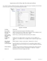
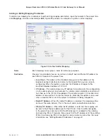
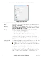
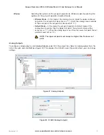
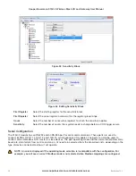
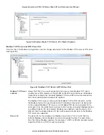
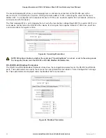
The following parameters can be configured for 915U-2 analog outputs.
Name
Enter a name for the analog output or leave the default name. The name can be up to
30 characters, including spaces.
Fail-safe Time (sec)
Sets the time the output needs to count down before activating the fail-safe state.
Receiving an update or a COS message will reset the fail-safe timer to its starting
value. When the fail-safe time elapses, the output is set to the fail-safe state (mA).
It is recommend the fail-safe time be configured for a little more than twice the
update time of the input that is mapped to it. That way the output will reset if it fails
to receive two update messages. Entering a zero as the fail-safe time will disable
fail-safe.
Fail-safe Value (mA)
Sets the value that the output will be set to when the fail-safe time elapses.
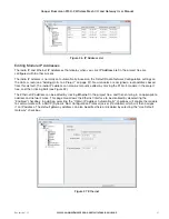
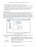
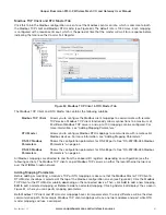
Adding Expansion I/O Modules
Additional 115S serial expansion I/O modules can be connected to the 915U-2 module if more I/O is required. The
RS-485 serial port on the 915U-2 is configured by default to communicate using the Modbus protocol. The default
serial parameters of the RS-485 port on the 915U-2 are 9600 baud, no parity, 8 data bits, 1 stop bit, which match
the defaults of the 115S serial expansion modules. These parameters can be changed, to increase poll speeds in
larger systems, but the serial module’s parameters must match that of the 915U-2 RS-485 port.
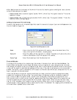
If more than three serial expansion I/O modules are added to the 915U-2 module, you will need to adjust the
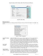
Maximum Connections setting for RS-485 or RS-232. To display these configuration screens, select the module in
the project tree and click
RS
-
485
or
RS
-
232
.
NOTE Reducing the Maximum Connections setting will slightly improve the serial scan time. However, you
need to make sure that the slave addresses fall within the Maximum Connections. If the Slave address is
above the Maximum Connections, it will not be polled.
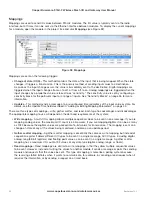
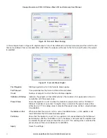
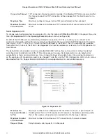
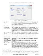
When you connect the serial expansion module, take note of the module address (the rotary switches on the
bottom of the module). This address will be used as an offset to locate the I/O within the 915U-2. Also make sure
that the termination switch is “on” (down) for the last module in the RS-485 loop.
NOTE Failure to terminate the RS
-
485 correctly will result in modules not operating correctly.
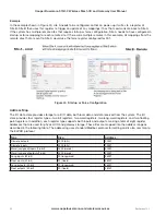
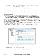
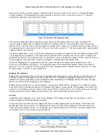
115S Expansion I/O Memory Map
The I/O data on the 115S module is read into memory locations according to their Modbus address. The maximum
number of Modbus addresses is 24. Each 115S module has an offset that applies to the location of its registers.
This offset is equal to the units Modbus address (selected on the rotary switch on the end of the 115S expansion
I/O module), multiplied by 20.
If the modules Modbus address is 15, the offset value will be 15 X 20 = 300.
For example, if connecting a 115S-11 (16 x DIO) with address #15:
• Digital input 1 will be at register location 10301
• Digital Output 1 will be at register location 301
If using a 115S-12 (8 x DIO & 8 AIN) with address 16:
• Digital input 1 will be at register location 10321
• Analog input 1 will be at register location 30321
For a detailed address map of the serial expansion I/O modules, see Appendix C.


