www.cooperbussmann.com/wirelessresources
Cooper Bussmann 915U-2 Wireless Mesh I/O and Gateway User Manual
23
Rev Version 1.2.2
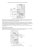
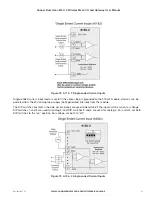
When active, the digital outputs provide a transistor switch to EARTH (Common). To connect a digital output, see
Figure 14. A bypass diode (IN4004) is recommended to protect against switching surges for inductive loads such as
relay coils. The digital channels D1–4 on the 915U-2 module can be used as pulse outputs with a maximum output
frequency of 10 kHz.
Digital Output Fail-safe Status
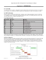
In addition to indicating the digital output status (on or off), the LEDs can also indicate a communications failure
by flashing the output LED. This feature can be used by configuring a fail-safe time and status via the I/O Digital
Output screen in the MConfig Utility (see “I/O Configuration” on page 47.)
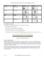
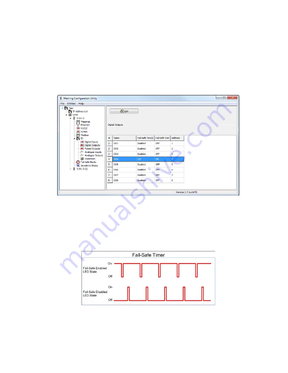
Figure 15 Digital Output Fail-safe Times
The fail-safe time is the time the output counts down before activating a fail-safe state. Normally this would be
configured for a little more than twice the update time of the mapping that is sending data to it. This is because the
fail-safe timer is restarted whenever it receives an update. If you send two successive updates and fail to receive
both of these messages, the timer counts down to zero and activates the fail-safe state.
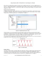
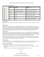
If the fail-safe state is enabled (on), the LED flashes briefly off and the digital output turns on. If the fail-safe state is
disabled (off), the LED flashes briefly on and the digital output turns off.
Figure 16 Fail-Safe State
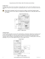
Analog Inputs
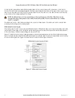
The 915U-2 module provides two floating differential analog inputs and two grounded single-ended analog inputs.
Analog inputs 1 and 2 will automatically measure current (0–20 mA) or voltage (0–25V), depending on what is
connected to the input. Analog inputs 3 and 4 must be configured to measure current (0–20 mA) or voltage (0–5V)
via the DIP switches on the configuration panel (see “Side Access Configuration Panel” on page 20).

